
Simple DC motor PWM speed control
The described circuit utilizes the 555 timer IC in an astable configuration, a common approach for generating square wave signals. The resistors and potentiometer values are critical in determining the timing characteristics of the circuit. The configuration allows for dynamic adjustment of the duty cycle, impacting the motor's operational characteristics.
When implementing this design, it is important to select a MOSFET or bipolar transistor that can handle the maximum current drawn by the motor. This ensures that the switching device operates within its safe limits, preventing damage due to thermal overload. The snubber diode serves to protect the switching device from back EMF generated when the motor is turned off, a common occurrence in inductive loads.
Heat dissipation is a significant consideration in this circuit design. The choice of heatsink for the MOSFET or bipolar transistor should be based on the expected power dissipation, which can be calculated from the product of the current flowing through the device and the voltage drop across it when conducting.
The inclusion of a series resistor with the snubber diode can fine-tune the motor's braking characteristics. This resistor introduces a voltage drop that can reduce the peak current during the turn-off phase, thereby improving efficiency and reducing wear on the components.
Overall, careful selection of components and consideration of thermal management will enhance the reliability and performance of the circuit, allowing for effective motor control across a range of applications.The 555 Ic is wired as an astable and the frequency is constant and independent of the duty cycle, as the total resistance (R charge + R discharge, notice the diode) is constant and equal to 22Kohm (givin a frequency of about 1Khz, notice the hum). When the potentiomenter is all up, the Rcharge resistance is 1, 0 Kohm (the diode prevents the capaci
tor to charge through the second potentiometer section and the other 1, 0 Kohm resistor), and Rdischarge is 21 Kohm, giving a 5% on duty cycle and a 1Khz frequency. When the potentiomenter is all down, the Rcharge resistance is 21, 0 Kohm (the diode prevents the capacitor to charge through the second potentiometer section and the other 1, 0 Kohm resistor), and Rdischarge is 1 Kohm, giving a 95% on duty cycle and a 1Khz frequency.
When the potentiomenter is at 50%, the Rcharge resistance is 11, 0 Kohm (the diode prevents the capacitor to charge through the second potentiometer section and the other 1, 0 Kohm resistor), and Rdischarge is 11 Kohm, giving a 50% on duty cycle and a 1Khz frequency. If you are disgusted by the 1Khz hum of the motor try to rise the frequency out of the audible range (replacing the potenziometer), but rembember that at higher frequency inductive reactance of motor rises so the the efficiency would drop.
Obviously the mosfet (or bipolar) must have enough current capability to drive the motor, so the drain (or collector) current must be equal to maximum motor current (at power supply voltage, when it is blocked). The snubber diode too, because it shorts the motor on the off cycle. Both mosfet (or bipolar) and diode have to be hooked (if you don`t want them cooked ;-) ) to a heatsink if the max motor current is more than 100 or 200mA.
I suggest to not stress to much the motor with too much work because it overheats both motor, transistor and diode. If you don`t want braking in the off cycle just place a resistor in series with the snubber diode, it should rise a bit efficiency but have more inertia when slowing the motor down.
The value of the resistor must be R=V(breakdown transistor) / Imax, and the power should be 5W. Mosfets have internal zener diode, but don`t count on it ;-) 🔗 External reference
Related Circuits
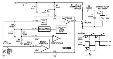
A temperature-controlled pulse-width-modulator (PWM) boost converter circuit diagram is illustrated in the following figure. This boost converter is designed to operate a 12V fan using a 5V supply while maintaining temperature control. The temperature-controlled PWM boost converter circuit operates by...
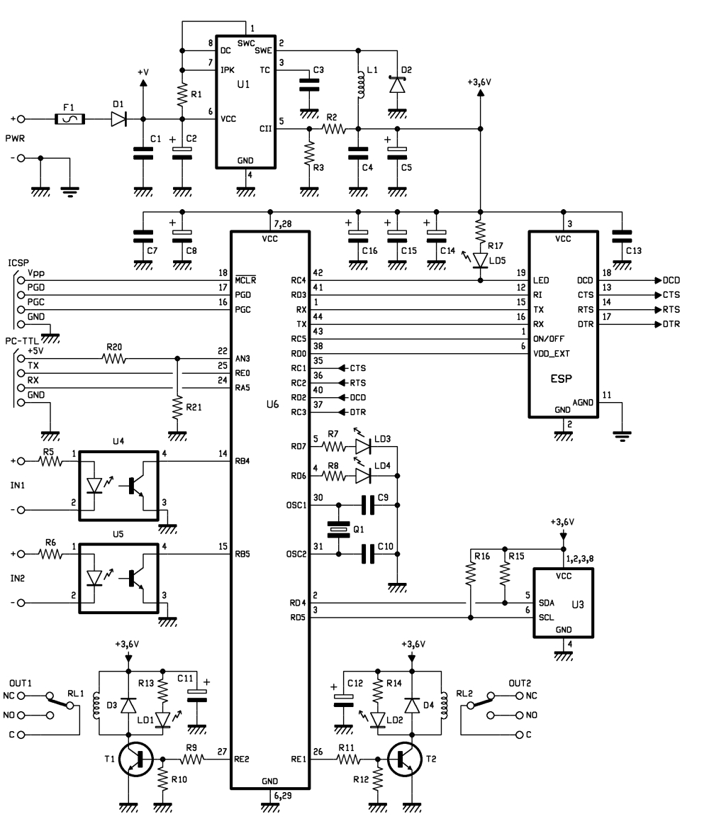
Connected to a burglar alarm or fire alarm, this device facilitates phone calls that play voice messages. It is controlled via DTMF actuators, allowing for immediate operation. In recent years, several telecontrols based on the SIM900 GSM module have...
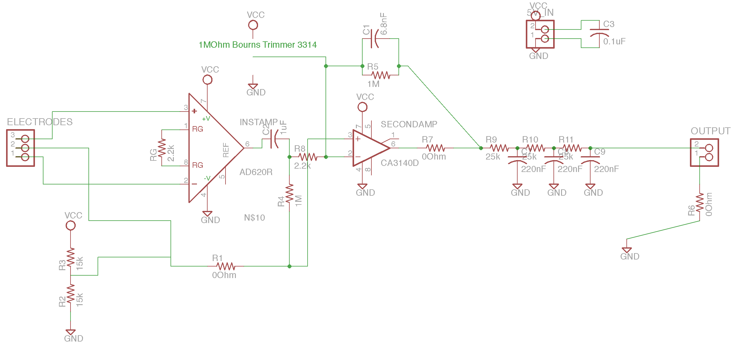
The circuit is based on the designs of Chipstein and Cornell, utilizing an instrumentation amplifier (AD620) to measure the voltage difference between two locations on the body. A second amplifier (CA3140) further amplifies this differential signal. A potentiometer is...
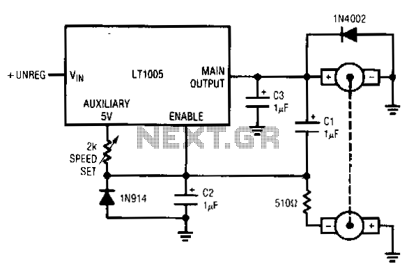
This circuit utilizes a tachometer to generate a feedback signal that is compared to a reference provided by the auxiliary output. Upon power application, the tachometer output is initially zero, allowing the regulator output to activate and supply current...
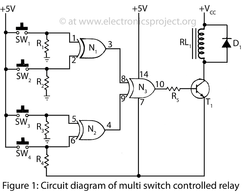
A Multi Switch Controlled Relay circuit is utilized to manage home appliances, featuring a circuit diagram that outlines the application of a multi switch-controlled relay using a single integrated circuit (IC) for various control functions. The Multi Switch Controlled Relay...
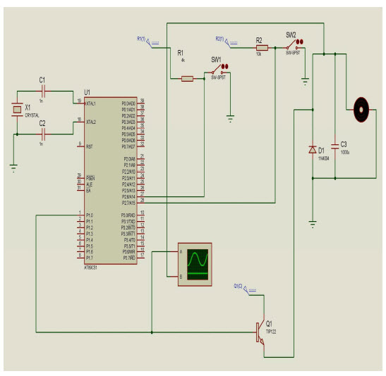
The objective of this project is to control the speed of a DC motor. The primary benefit of utilizing a DC motor is the ability to modify the Speed-Torque relationship to nearly any desired form. To facilitate speed control,...