
PWM Fan Controller schematic
More: The system is quite simple, a temperature sensor will be connected to the input of a microcontroller. There will be two outputs, one for operating the fan and one for operating a status LED. During construction a serial output will also be used for debugging purposes. The LM35 temperature sensor package being used is the TO-92, it is small enough for this project and is leaded so that we can easily connect it to some wires. It is also nice since we can extend it by simply plugging it into a 0.1 inch female wire harness. This is a Celsius device and since the output is 10mV per degree it is very simple to calculate the temperature. It is even nice and simple to directly view the temperature on a multimeter as can be seen in the video. The LM35 outputs 10mV per degree Celsius, this can be read very easily on the meter but unfortunately isn’t quite that simple to read it within the microcontroller. The output of the LM35 is connected to an ADC (analog to digital converter) so that we can get a usable reading from it, but first we need to do a small calculation.
The analog input has a range of 0 to 5 volts and the digital resolution is 10 bits. This means that the 0 to 5 volt range will be represented by a number from 0 to 1023 in the microcontroller. If we divide 5 volts by 1024 we get the number of volts per digital increment. In this case it is 0.004883 volts per increment. So if the voltage was 1 volt on the microcontroller pin we would expect to have a reading of around 204 as the digital number (1/0.004883).
To convert the digital value to a degrees Celsius number we need to do a bit of math. If we take the digital result and multiply it by 49 then divide it by 100 we will get a result that is very close to the correct result. The calculation looks a bit weird since we are working with integer math. With integer math the information after the decimal is lost. For example 25/3 would be 8 (not 8.333).
Here is a full example. If we have a temperature of 15 degrees Celsius the voltage out of the LM35 would be around 10mV * 15 = 0.15V we know that each 0.004883 volts is one count for the digital side of the ADC therefore 0.15V / 0.004883 V = 30.73 this would provide a value of simple 30. Finally if we use the formula 30 * 49 / 100 = 14.7 but it would be stored as 14.
The PWM Fan Controller circuit utilizes a PIC 12F675 microcontroller, which serves as the central processing unit for managing the temperature readings and controlling the fan operation based on those readings. The LM35 temperature sensor, which outputs a voltage proportional to the temperature in degrees Celsius, is connected to one of the analog input pins of the microcontroller. The LM35's output voltage varies linearly at 10 mV per degree Celsius, allowing for straightforward temperature calculations.
The microcontroller features an integrated 10-bit ADC that converts the analog voltage from the LM35 into a digital value ranging from 0 to 1023. This digital representation is then processed to derive the corresponding temperature in degrees Celsius. The calculation involves multiplying the digital value by 49 and dividing by 100, accommodating the limitations of integer math within the microcontroller.
The fan control mechanism is implemented through a PWM signal generated by the microcontroller based on the temperature readings. As the temperature increases, the duty cycle of the PWM signal is adjusted to increase the fan speed proportionally, thereby enhancing cooling efficiency. Additionally, a status LED is connected to another output pin on the microcontroller, providing visual feedback on the system's operational status.
A serial output is also incorporated into the design for debugging purposes, enabling the monitoring of temperature readings and system performance during development. The TO-92 package of the LM35 sensor allows for easy integration into the circuit, facilitating connections through a 0.1 inch female wire harness. Overall, this design offers a compact and effective solution for managing fan operation based on real-time temperature measurements.The heart of the PWM Fan Controller is a PIC 12F675 microcontroller. This microcontroller is reading the analog output of a LM35 temperature sensor using a ADC (analog to digital converter) . The resulting digital value is converted to a temperature and a fan is powered proportionally to how hot the sensor is.
The sensor is mounted against the hard drive chassis so it is measuring the actual drive temperature and not just the air temperature inside the housing. The system is quite simple, a temperature sensor will be connected to the input of a microcontroller. There will be two outputs, one for operating the fan and one for operating a status LED. During construction a serial output will also be used for debugging purposes. The LM35 temperature sensor package being used is the TO-92, it is small enough for this project and is leaded so that we can easily connect it to some wires.
It is also nice since we can extend it by simply plugging it into a 0.1 inch female wire harness. This is a Celsius device and since the output is 10mV per degree it is very simple to calculate the temperature. It is even nice and simple to directly view the temperature on a multimeter as can be seen in the video.
The LM35 outputs 10mV per degree Celsius, this can be read very easily on the meter but unfortunately is isn’t quite that simple to read it within the microcontroller. The output of the LM35 is connected to an ADC (analog to digital converter) so that we can get a usable reading from it, but first we need to do a small calculation.
The analog input has a range of 0 to 5 volts and the digital resolution is 10 bits. This means that the 0 to 5 volt range will be represented by a number from 0 to 1023 in the microcontroller. If we divide 5 volts by 1024 we get the number of volts per digital increment. In this case it is 0.004883 volts per increment. So if the voltage was 1 volt on the microcontroller pin we would expect to have a reading of around 204 as the digital number (1/0.004883).
To convert the digital value to a degrees Celsius number we need to do a bit of math. If we take the digital result and multiply it by 49 then divide it by 100 we will get a result that is very close to the correct result. The calculation looks a bit weird since we are working with integer math. With integer math the information after the decimal is lost. For example 25/3 would be 8 (not 8.333). Here is a full example. If we have a temperature of 15 degrees Celsius the voltage out of the LM35 would be around 10mV * 15 = 0.15V we know that each 0.004883 volts is one count for the digital side of the ADC therefore 0.15V / 0.004883 V = 30.73 this would provide a value of simple 30.
Finally if we use the formula 30 * 49 / 100 = 14.7 but it would be stored as 14. 🔗 External reference
Related Circuits
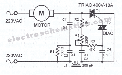
This triac-based 220V AC motor speed controller circuit is designed for controlling the speed of small household motors, such as drill machines. The motor speed can be adjusted by altering the setting of P1, which determines the phase of...
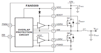
The schematic illustrates a typical application circuit for the FAN5009, a dual bootstrapped 12V high-frequency MOSFET driver. When integrated with a multi-phase PWM controller and power MOSFETs, it can form a complete core voltage regulator for microprocessors, as specified...
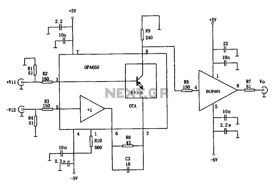
The circuit presented is a 400MHz broadband differential amplifier. It comprises two main components: the incoming broadband differential amplifier integrated circuit OPA660 and the buffer amplifier BUF601. The voltage gain of the circuit is given by the formula Av...
Electronic Project EPROM Emulator. This EPROM Emulator was designed to complement the EPROM Programmer (Mark 2). The EPROM Emulator serves as a versatile tool for testing and developing electronic circuits that utilize EPROM (Erasable Programmable Read-Only Memory) chips. This device...
Probably the best advantage is its very small size and the fact that it can run off the power supply of the circuit being tested. Although it has a low frequency range, it can still be used for most...

The 10K resistor is necessary if the receiver is to mute (squelch) under no-signal conditions. An additional 100K resistor can be added in series with this resistor to create an adjustable squelch. This circuit is designed to drive a...
Warning: include(partials/cookie-banner.php): Failed to open stream: Permission denied in /var/www/html/nextgr/view-circuit.php on line 713
Warning: include(): Failed opening 'partials/cookie-banner.php' for inclusion (include_path='.:/usr/share/php') in /var/www/html/nextgr/view-circuit.php on line 713