
Mini Oscilloscope schematic

The LEDs are multiplexed by a 4017 driven by the timebase. This arrangement reduces the current requirements considerably, no mean consideration when operating from the power supply of the device under test.
With a device like this, making the unit as small as possible is obviously a consideration. Katz decided to make his own box out of perspex so that he could make it just as big as the circuit board, and no bigger. He was also able to give the thing a fancy shape rather like a bought one.
On the basis that this project had the highest combination of imagination, design ingenuity, construction, and documentation, we made it the national winner.
The circuit described is a compact oscilloscope designed to visualize analog waveforms. It operates on a low frequency range, making it suitable for a variety of testing applications. The primary advantage of this design is its small footprint, allowing it to be powered directly from the circuit under test, which enhances portability and convenience. The display consists of a matrix of 100 LEDs, which, while limited in resolution, is adequate for visualizing most waveforms encountered in practical scenarios.
The core of the timebase is implemented using a 555 timer IC, which generates a horizontal sweep necessary for waveform display. This component is well-known for its reliability and ease of use in timing applications. The vertical amplification of the signal is handled by a 3914 operational amplifier, which is equipped with a trimpot for fine-tuning the vertical scale of the displayed waveform. This simplicity in design contributes to the overall effectiveness of the oscilloscope.
To manage the LED display, a 4017 decade counter is employed to multiplex the LEDs, which significantly reduces the current draw of the circuit. This is a critical feature when considering the power constraints of operating from the device under test. The multiplexing technique allows for a dynamic display of the waveform without necessitating high power consumption.
The enclosure of the oscilloscope is constructed from perspex, allowing for a custom fit that aligns closely with the dimensions of the circuit board. This design choice not only minimizes the physical size of the unit but also provides a visually appealing appearance, akin to commercially available oscilloscopes.
Overall, this project exemplifies ingenuity in electronic design, combining functionality with aesthetic considerations, and demonstrates a solid understanding of the principles of waveform visualization. The combination of compact size, efficient power usage, and effective display capabilities contributed to its recognition as a national winner in the competition.Probably the best advantage is its very small size and the fact that it can run off the power supply of the circuit being tested. Although it has a low frequency range, it can still be used for most circuits. Its poor resolution will still allow for most waveforms to be visualized. This was pretty much the judges' own assesment of Katz's project. It uses a matrix of 100 LED's for a display, and does suffer from being slow and having rather poor resolution.
Still we could display a sine wave running at 500Hz without trouble, that that's not all that dissimilar to commercial solid state osscilloscopes. The circuit displays an understanding of the mechanics of displaying an analogue waveform. The timebase is simply a 555 generating a horizontal sweep, while the vertical amplifier is 3914 with a trimpot on the front. It's extremely simple, but it works. The LEDs are multiplexed by a 4017 driven by the timebase. This arrangement reduces the current requirements considerably, no mean consideration when operating from the power supply of the device under test.
With a device like this, making the unit as small as possible is obviously a consideration. Katz decided to make his own box out of perspex so that he could make it just as big as the circuit board, and no bigger. He was also able to give the thing a fancy shape rather like a bought one. On the basis that this project had the highest combination of imagination, design ingenuity, construction and documentation, we made it the national winner.
🔗 External reference
Related Circuits
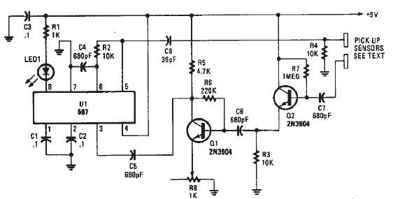
A simple proximity detector electronic project can be designed using this schematic circuit. This project utilizes a tone decoder integrated circuit (NE567) that provides a signal with a frequency of approximately 100 kHz. When an object is placed near...
The LM35 Smart Heater Controller Schematic features a compact circuit designed around the well-known 3-Pin Integrated Temperature Sensor LM35 (IC1) from National Semiconductor. Additionally, a widely used BiMOS Op-amp CA3140 (IC2) is employed to monitor the temperature sensor's output,...

The LMP91200 is a configurable sensor analog front-end (AFE) designed for managing low-power analytical sensing applications, specifically for 2-electrode sensors. This device offers all the necessary functionality to detect changes based on a delta voltage from the sensor. It...
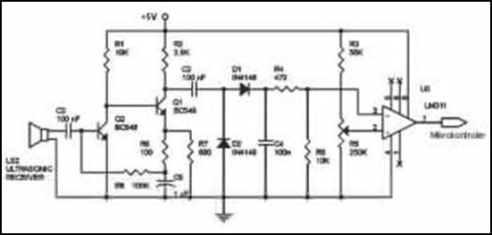
Ultrasonic receivers detect an ultrasonic signal emitted by an ultrasonic transmitter at a specific frequency. The received signal is filtered using a band-pass filter circuit that allows only the predetermined frequency range to pass. The output signal is then...
Here are some schematics and information that can be difficult to locate elsewhere. If there are schematics that should be included in this collection, please feel free to reach out. The intention is to expand this collection over time,...
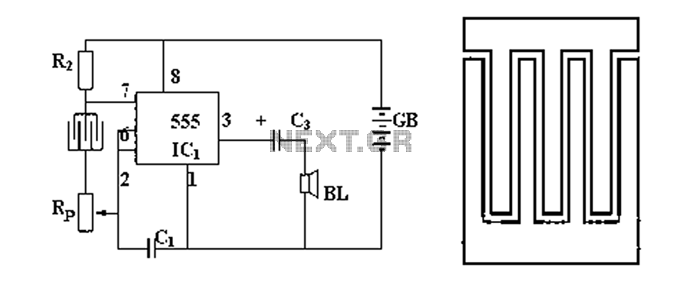
Figure 1 illustrates a circuit diagram related to an audio circuit that incorporates a resistance between two leads connected to a rain alarm probe. Figure 2 demonstrates the connection of a capacitor to the probe within the audio circuit....