
Pwm Motor-Drive Circuit Circuit
The described circuit utilizes pulse width modulation (PWM) to effectively control the speed of a small DC motor. By varying the duty cycle of the PWM signal, the average voltage applied to the motor can be adjusted, allowing for precise speed control without the need to alter the supply voltage. This method is advantageous as it minimizes power loss and heat generation compared to linear voltage regulation methods.
The circuit typically consists of a microcontroller or a dedicated PWM controller that generates the PWM signal. This signal is fed into a transistor or a MOSFET, which acts as a switch to control the flow of current to the motor. The duty cycle, defined as the ratio of the on-time to the total cycle time, can be adjusted programmatically or through a variable resistor, enabling a smooth transition between different speeds.
In addition to the motor, the circuit may include protective elements such as diodes to prevent back EMF from damaging the switching components and capacitors for filtering the PWM signal to reduce electrical noise. Feedback mechanisms, such as tachometers or encoders, can also be integrated to provide real-time speed monitoring and closed-loop control, ensuring optimal performance and preventing stalling under varying load conditions.
Overall, this circuit design effectively balances efficiency and performance, making it suitable for applications requiring variable speed control of small DC motors in robotics, automation, and other electronic systems. This circuit will drive a small dc motor over a wide range of speeds without stalling by controlling the duty cycle of the motor, rather than the supply voltage. 🔗 External reference
Related Circuits
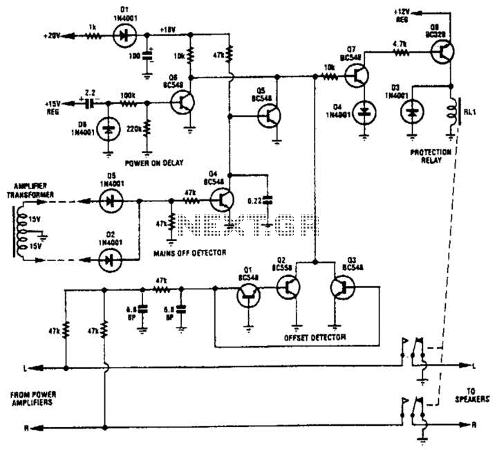
Transistors Q1, Q2, and Q3 monitor the two outputs of the stereo amplifier. If the offsets exceed 2 V, Q7 is turned off, which in turn deactivates Q8 and the normally on relay. Diodes D2 and D5, along with...
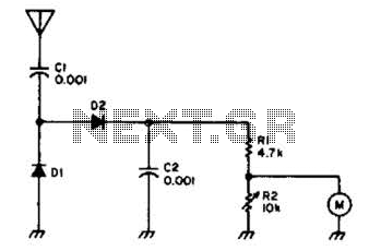
Useful for checking transmitters and antennas, this circuit utilizes a voltage-doubling detector consisting of diodes D1 and D2, which can be HP 5082-2800 hot carrier types or alternatives such as 1N34 or IN82. The circuit incorporates a 100-mA meter...
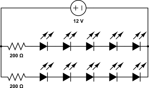
A 12V power supply is available, and there is a need to power LEDs with a forward voltage of 2V. It is questioned whether only six LEDs can be powered or if the cathode of one LED can be...
The TBA120 Series integrated circuits (ICs) offer a high-gain limiting intermediate frequency (IF) amplifier and a quadrature coincidence detector in a single package. These ICs are primarily designed for the extraction of television intercarrier sound, which is frequency modulated...
Camping today often involves various electronic accessories for daily activities or entertainment. Typically, a portable battery charger and a power inverter are used to ensure a well-organized campsite where both adults and children can comfortably use their electronic devices....
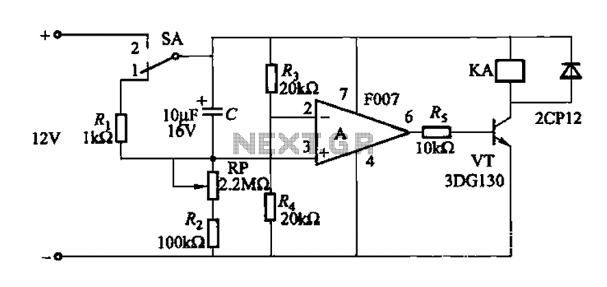
A delay circuit utilizing an operational amplifier functions as a comparator, providing high timing accuracy. The timer's delay range is from 1 to 30 seconds. The delay time is determined by resistors Ri, RP, and capacitor C. By adjusting...