
Simple Field Strength Meter I Circuit
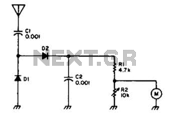
This circuit is designed to facilitate the testing of transmitters and antennas by employing a voltage-doubling mechanism. The primary components, diodes D1 and D2, play a crucial role in the detection process. The HP 5082-2800 diodes are known for their efficiency in high-frequency applications due to their hot carrier characteristics. Alternatively, the circuit can utilize standard silicon diodes such as the 1N34 or IN82, which are readily available and offer sufficient performance for most transmitter testing applications.
The voltage-doubling configuration allows the circuit to effectively increase the voltage output from the antenna or transmitter, making it easier to measure the signal strength with the integrated 100-mA meter movement. This meter is calibrated to provide accurate readings of the voltage levels, which correspond to the power output of the transmitter or the efficiency of the antenna.
In practical applications, the circuit can be connected directly to the output of a transmitter or the feed point of an antenna. The readings obtained from the meter can assist engineers in diagnosing performance issues, optimizing antenna placement, or verifying transmitter output levels. The design emphasizes simplicity and reliability, making it a valuable tool for both amateur radio operators and professional technicians in the field of electronics. Useful for checking transmitters and antennas, this circuit uses a voltage-doubling detector D1 and D2 (HP 5082-2800 hot carrier types). D1 and D2 can also be type 1N34 or IN82. is a 100-mA meter movement. 🔗 External reference
Related Circuits
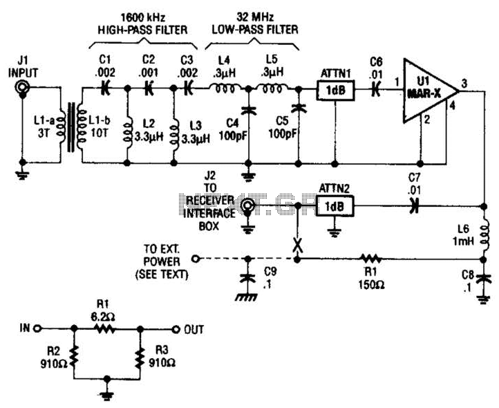
The HF/SW receiver preamplifier consists of a broadband toroidal transformer (LI-a and Ll-b), an LC network featuring a 1600-kHz high-pass filter and a 32-MHz low-pass filter, inductors L2 and L3 (26 turns of #26 enameled wire wound on an...
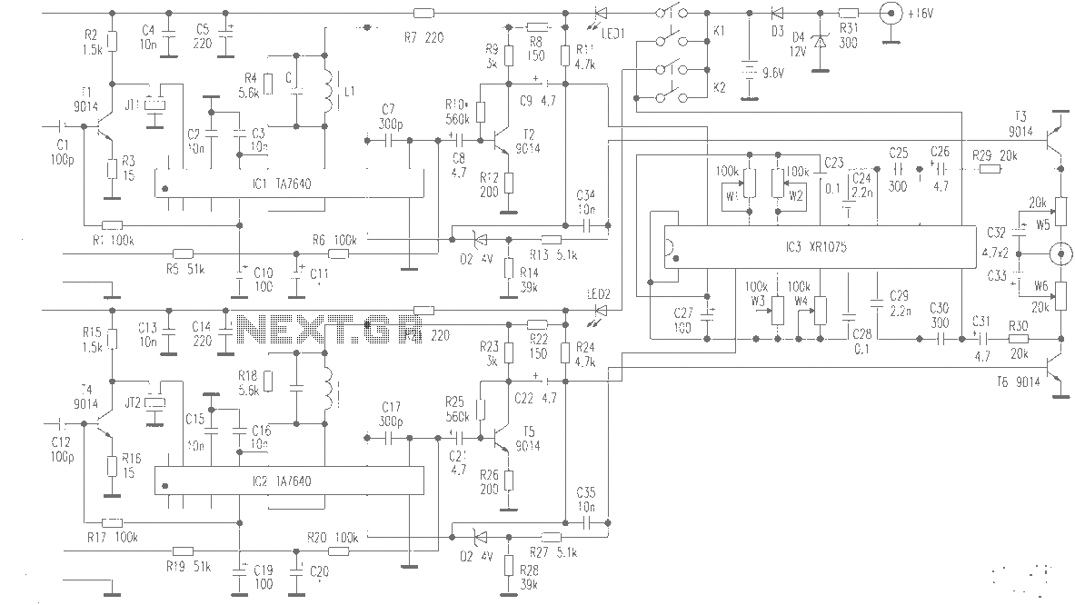
The production of high-quality wireless microphones is a common aspiration among enthusiasts, but achieving a high-performance receiver is challenging. This project explores the use of salvaged FM radio cassette players to enhance an XR1075 audio processor, leading to the...
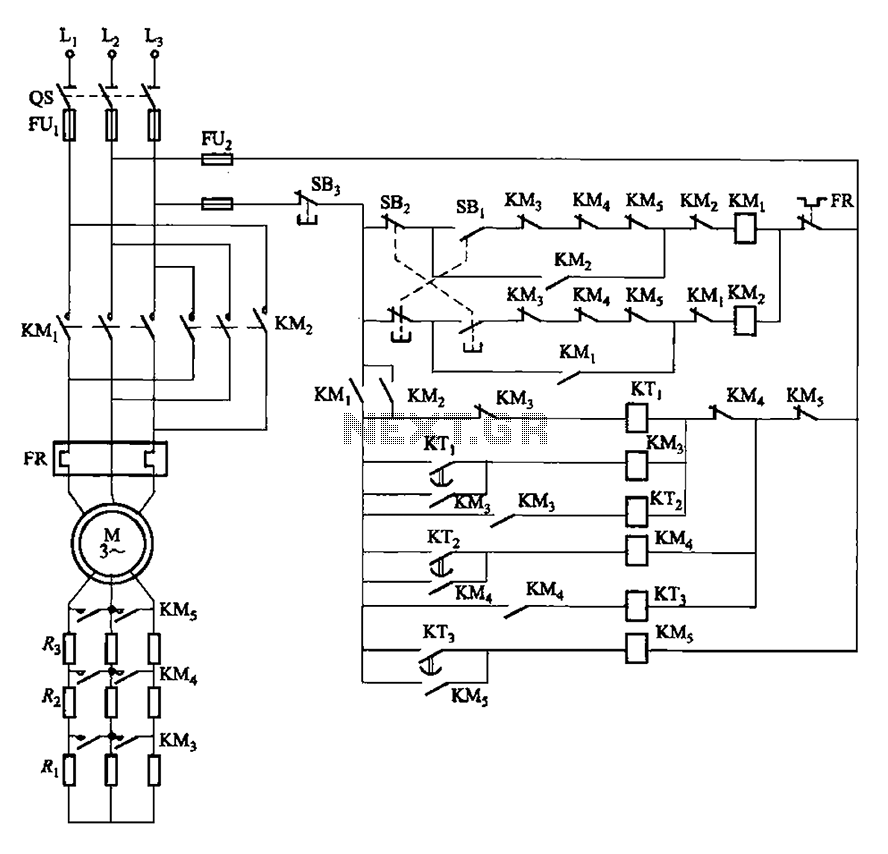
The circuit depicted in Figure 3-162 includes several components: SBi serves as the forward start button, SBz functions as the reverse start button, and SB3 is designated as the stop button. The resistance levels for the start switches are...

The circuit utilizes a tuned circuit for frequency selection, designed to operate at approximately 51 kHz. The 2N3565 transistor amplifies the output generated by the tuned circuit. The described circuit operates on the principle of resonance, where the tuned circuit...
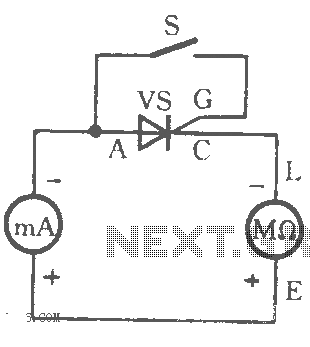
The table illustrates the capability to trigger the thyristor circuit diagram. The thyristor circuit diagram serves as a fundamental component in various electronic applications, particularly in power control and switching. A thyristor is a four-layer semiconductor device that functions as...
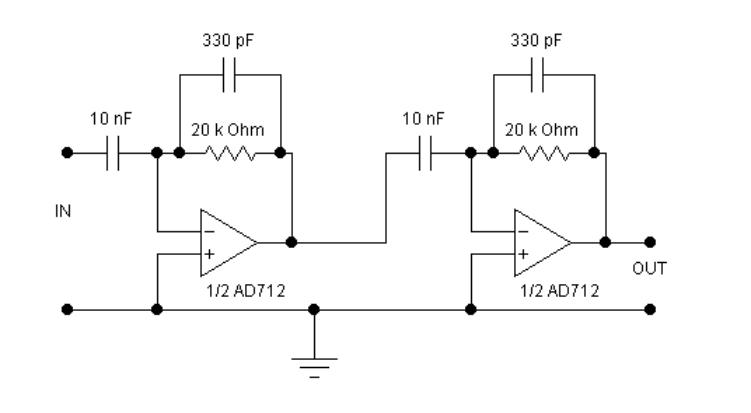
The circuits examined thus far rely on linear feedback for their operation. The magnitude of the signal returned to the negative input is always strictly proportional to the output voltage. Consequently, within the limits defined by the operational amplifier...