
PWM power controller

This circuit design effectively demonstrates the principles of pulse-width modulation (PWM) using a 555 timer and op-amp comparator configuration. The 555 timer is configured in astable mode to produce a sawtooth waveform, which is essential for generating the PWM signal. The capacitor charges and discharges in a linear fashion, creating the sawtooth waveform, while the potentiometer provides an adjustable reference voltage for the op-amp comparator.
The op-amp's role is critical, as it compares the sawtooth waveform with the reference voltage from the potentiometer. When the sawtooth voltage exceeds the reference voltage, the op-amp switches its output state, generating a square wave that modulates the power transistor. The duty cycle of this square wave is directly affected by the potentiometer setting, allowing for fine adjustments in power delivery to the load.
The power transistor acts as a switch that rapidly turns the load on and off, effectively controlling the average power delivered to the load. This method is highly efficient, as the power transistor operates in saturation and cutoff, minimizing heat generation compared to resistive methods. The use of parallel op-amps ensures that sufficient current is available to drive the transistor into saturation, enhancing the circuit's overall performance.
The incorporation of diodes between the op-amp outputs and the transistor base serves a dual purpose: it protects the op-amps from excessive current draw and ensures that the transistor can be fully turned off when the op-amps output low. This careful consideration of component interactions ensures reliable operation and longevity of the circuit.
For practical applications, this circuit can be utilized in various scenarios where variable power control is required, such as in dimming lamps or controlling motor speeds. The ability to visualize the waveforms through experimentation enhances understanding and allows for optimization of circuit parameters for specific applications.This circuit uses a 555 timer to generate a sawtooth voltage waveform across a capacitor, then compares that signal against a steady voltage provided by a potentiometer, using an op-amp as a comparator. The comparison of these two voltage signals produces a square-wave output from the op-amp, varying in duty cycle according to the potentiometer`s
position. This variable duty cycle signal then drives the base of a power transistor, switching current on and off through the load. The 555`s oscillation frequency is much higher than the lamp filament`s ability to thermally cycle (heat and cool), so any variation in duty cycle, or pulse width, has the effect of controlling the total power dissipated by the load over time.
Controlling electrical power through a load by means of quickly switching it on and off, and varying the "on" time, is known as pulse-width modulation, or PWM. It is a very efficient means of controlling electrical power because the controlling element (the power transistor) dissipates comparatively little power in switching on and off, especially if compared to the wasted power dissipated of a rheostat in a similar situation.
When the transistor is in cutoff, its power dissipation is zero because there is no current through it. When the transistor is saturated, its dissipation is very low because there is little voltage dropped between collector and emitter while it is conducting current.
PWM is a concept easier understood through experimentation than reading. It would be nice to view the capacitor voltage, potentiometer voltage, and op-amp output waveforms all on one (triple-trace) oscilloscope to see how they relate to one another, and to the load power. However, most of us have no access to a triple-trace oscilloscope, much less any oscilloscope at all, so an alternative method is to slow the 555 oscillator down enough that the three voltages may be compared with a simple DC voltmeter.
Replace the 0. 1 µF capacitor with one that is 100 µF or larger. This will slow the oscillation frequency down by a factor of at least a thousand, enabling you to measure the capacitor voltage slowly rise over time, and the op-amp output transition from "high" to "low" when the capacitor voltage becomes greater than the potentiometer voltage. With such a slow oscillation frequency, the load power will not be proportioned as before. Rather, the lamp will turn on and off at regular intervals. Feel free to experiment with other capacitor or resistor values to speed up the oscillations enough so the lamp never fully turns on or off, but is "throttled" by quick on-and-off pulsing of the transistor.
When you examine the schematic, you will notice two operational amplifiers connected in parallel. This is done to provide maximum current output to the base terminal of the power transistor. A single op-amp (one-half of a 1458 IC) may not be able to provide sufficient output current to drive the transistor into saturation, so two op-amps are used in tandem. This should only be done if the op-amps in question are overload-protected, which the 1458 series of op-amps are.
Otherwise, it is possible (though unlikely) that one op-amp could turn on before the other, and damage result from the two outputs short-circuiting each other (one driving "high" and the other driving "low" simultaneously). The inherent short-circuit protection offered by the 1458 allows for direct driving of the power transistor base without any need for a current-limiting resistor.
The three diodes in series connecting the op-amps` outputs to the transistor`s base are there to drop voltage and ensure the transistor falls into cutoff when the op-amp outputs go "low. " Because the 1458 op-amp cannot swing its output voltage all the way down to ground potential, but only to within about 2 volts of ground, a direct connection from the op-amp to the transistor would mean the transistor would never fully turn off.
Ad 🔗 External reference
Related Circuits
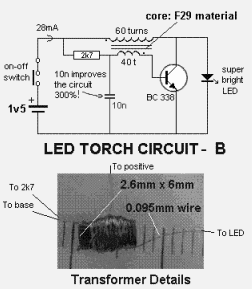
This circuit illustrates a 1.5V LED power supply circuit diagram. Features include the requirement of a step-up transformer (40:60) for easy provision. Components include an integrated circuit (IC). The described circuit functions as a power supply specifically designed for driving...
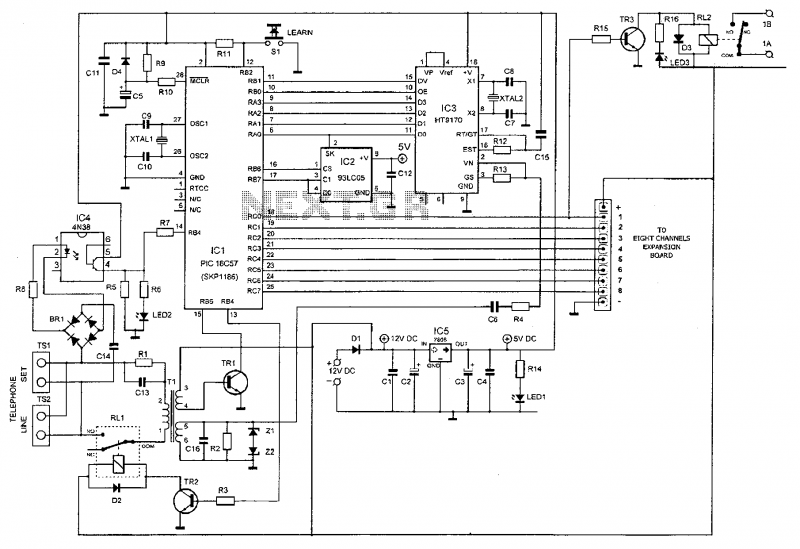
This device enables remote control of various appliances (up to eight with suitable add-on expansion boards) such as lights, water heaters, air conditioning, plant watering systems, alarms, etc., via a relay. It allows users to perform actions such as...
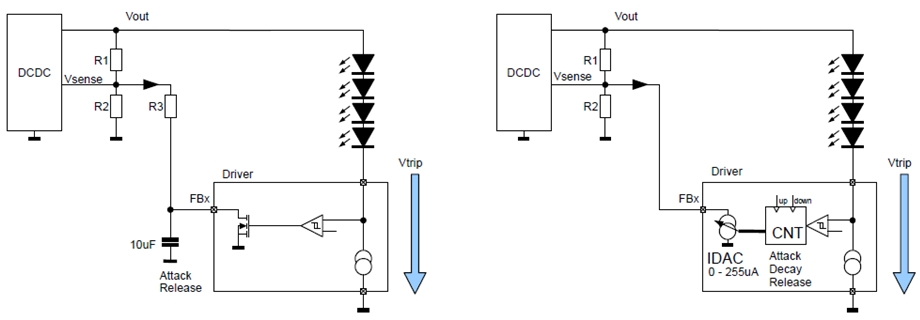
New design techniques in LED driver circuits promise to deliver significant energy savings that will help TV manufacturers meet stringent power consumption requirements. The advancement of LED driver circuits through innovative design techniques has the potential to yield substantial energy...
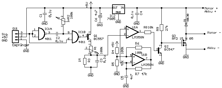
No description available. More: Q1, Q2: Standard-Transistoren D1: SB130 Q3: RFD 15 N 05 IC1A: CD4011B (if SMD) IC1B: detto The provided components suggest a basic electronic circuit that incorporates both transistors and integrated circuits, along with a diode. The circuit...
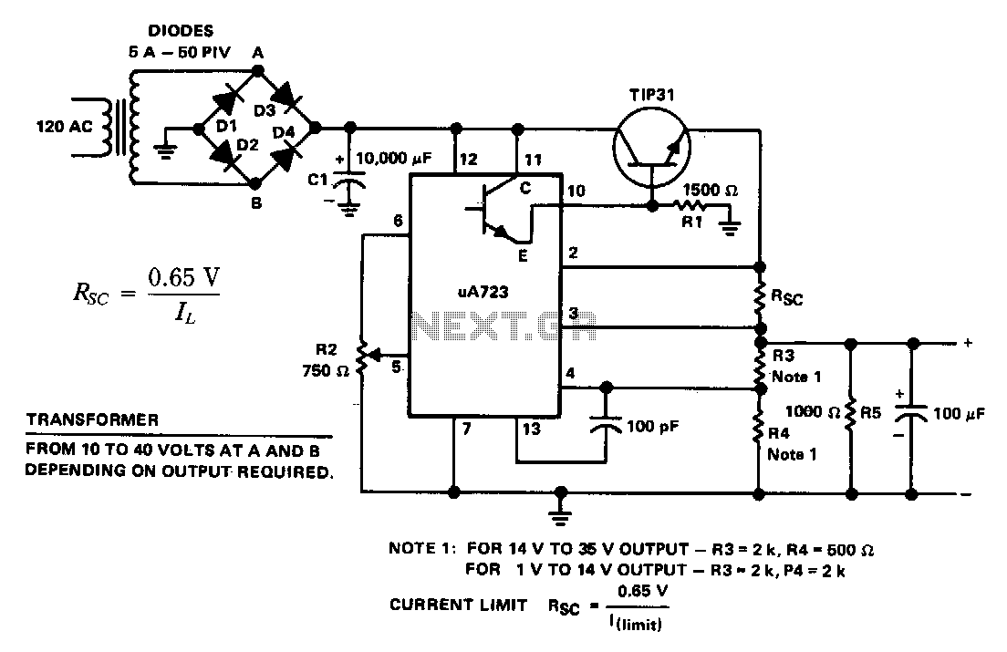
The supply 6-66 can be utilized for output voltages ranging from 1 to 35 V. The line transformer must be selected to provide approximately 1.4 times the desired output voltage from the positive side of filter capacitor C1 to...
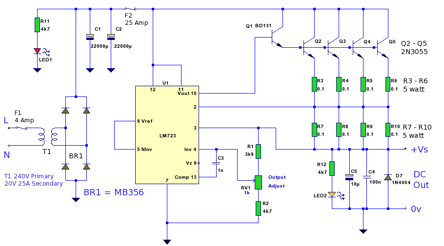
A 12 Volt high current 20 Amp power supply. The output voltage is variable from 12.2 Volt to 14.4V, allowing it to be set for any device requiring voltage and current in that range. This power supply unit (PSU)...