
Microcontroller Based Telephone Remote Control Circuit
- Control (ON-OFF) of an appliance (up to eight with expansion) through telephone.
- Positive confirmation of the device state by sound signals.
- Four-digit security access code.
- Power requirements: 12VDC / 0.5A.
- Relay rating: 230V 10A.
- Expansion to up to eight channels via a relay board.
- Can be used with a GSM unit if there is no telephone line available.
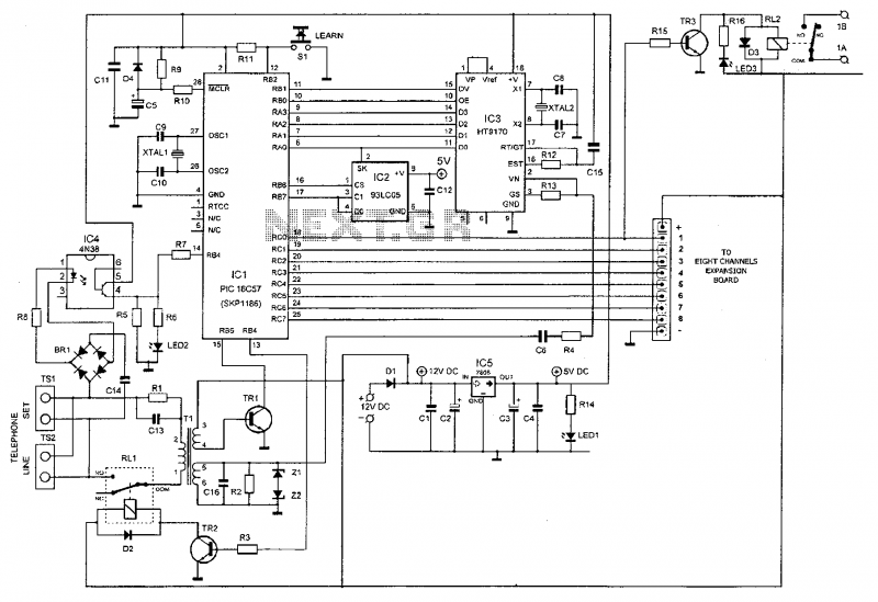
The circuit comprises four distinct stages, identifiable in the schematic:
- The first stage is the power supply, utilizing the LM7805 voltage regulator (IC5) to provide +5 VDC for the microprocessor and DTMF decoder circuits, while supplying 12 VDC to the transistors controlling the relays and relay coils.
- The second stage centers around the HT9170 DTMF decoder IC (IC3), responsible for identifying the access code and commands sent to the system.
- The third stage involves the microprocessor PIC16C57 (IC1) and its memory component 93LC46 (IC2). This stage interprets and executes the received commands.
- The fourth stage consists of a control circuit with a relay rated at 10 A, capable of activating or deactivating any connected device based on commands sent via telephone to the microcontroller.
Construction considerations include avoiding overheating of the tracks to prevent damage and using long-nose pliers when soldering sensitive components to dissipate heat. The circuit should be connected to a 12V DC power supply.
Programming and control are conducted through a telephone. The process includes connecting the device to a digital telephone line, dialing the number, waiting for a confirmation tone, entering the access code, and executing commands to activate or deactivate connected appliances. The system provides feedback through tones indicating the state of the device.
To change the access code, a telephone connected in parallel to the device is used to press the LEARN button, followed by entering a new four-digit code.
For troubleshooting, checks should be performed for cold joints, soldering errors, external connections, component placement, and voltage supply. If issues persist, contacting the retailer for service is recommended.
The parts list includes specific resistors, capacitors, diodes, LEDs, transistors, microcontrollers, and relays necessary for constructing the device. The remote controller can operate with either a digital telephone landline or a compatible GSM module, enhancing flexibility in locations without a permanent telephone connection. Expansion boards allow for the addition of more relays, accommodating a total of eight devices.This device allows you to control remotely any (with suitable add-on expansion boards, up to eight) device, such as lights, water heaters (boiler), air-condition, plant watering, alarms, etc via a relay. By using it you can for example water the garden at your country house from the convenience of your living-room, or you may turn on the water heater, or the air—condition at home from your offices so by the time you get there, there will be hot water and the ambient temperature will be as you prefer it.
This is done by means of this circuit and a simple digital telephone line or a GSM unit. It is secure as it has a four digit access code and you get a positive confirmation that your command was accepted. Operation of the device is simple, as simple as pressing the proper key sequence on a digital telephone keypad.
The system requires a digital line as it is controlled by the. DTMF codes used in modern telephones and CANNOT be used with with the pulses used over the old analogue telephone lines.
TECHNICAL SPECIFICATIONS
- - Control (ON-OFF) of an appliance (up to eight with expansion) through telephone.
- - Positive confirmation of the device state by sound signals.
- - Four-digit security access code.
- - Power requirements: 12VDC / 0,5A
- - Relay rating: 230V 110A
- - Expansion to up to eight channels via a relay board.
- - Can be used with a GSM unit if there is no telephone line available.
HOW IT WORKS
The circuit consists of four different stages, easily recognized on the schematic:
- The first stage is the power supply. it uses the voltage regulator LM7805 (IC5), in order to provide +5 VDC to the microprocessor and the
DTMF decoder circuits, and also supplies with 12 VDC the transistors controlling the relays and the relay coils themselves.
- The second stage is built around the HT9170 (IC3) which is a DTMF decoder IC.
This stage is responsible for the identification of the access
code and the commands sent to the system.
- The third stage is built around the microprocessor PIC16657 (IC1) and its memory the 93LC4BB (IC2). This is the part of the circuit
which "understands" and executes the command received.
- Finally.
the fourth stage consists control circuit with a relay having contacts rated at 10 A which can activate (turn ON) or deactivate (turn OFF)
any device connected to it. following the commands send via telephone to the micro-controller.
CONSTRUCTION
- Take care not to overheat the tracks as it is very easy to lift them from the board and break them
- When you are soldering a sensitive component it is good practice to hold the lead from the component side of the board with a pair of long
nose pliers to divert any heat that could possibly damage the component.
- Connect the circuit to a 12V DC power supply +12V.
PROGRAMMING
The programming and control of the unit is done via telephone.
To do this. follow the next steps:
1. Connect the device to a digital telephone line. From another line (or a mobile), dial the number of the line that is connected to the device.
2. After the third ring you will hear two short tones (beep—beep).
3. Enter the key sequence of the access code (the Initial code number is 1234, a number which you may change easily later on).
4. If you have entered the access code correctly, you will hear again two short tones (beep-beep). otherwise you will hear-a protracted tone
(beeeeep). If the access code is not entered correctly. after the third attempt. the device will drop the line and terminate the connection. This is
a safety measure against tampering with the controller.
5. Once you achieve a successful connection to the remote control device, press *1. This way the device activates the relay turning the
appliance connected to it ON. If you want to deactivate the relay. simply press #1.
6. If you want to check the state of the system, enter 1. If you hear a protracted tone (beeeeep) the device is OFF. If you hear two short tones
(beep-beep), the device is ON.
CHANGE OF ACCESS CODE
If you want to change the original four digit access code, pick up the handset of a telephone connected in parallel to the device, and press the
button switch LEARN (S1).
When you hear four short tones (beep-beep—beep-beep) you may enter the new four digit access code. You will
hear four short tones again. which means that the change has been successfully accepted.
IF IT DOESN'T WORK
- Check your work for cold joints, bridges across adjacent tracks or soldering flux residues that may cause problems.
- Check all the external connections to and from the circuit.
- See that there are no missing or misplaced components.
- Make sure that all the polarized components have been soldered the right way round.
- Make sure that the supply has the right voltage and polarity.
- Check your project for faulty or damaged components.
If everything checks and your project still fails to work, please contact your retailer and the Smart Kit Service will repair it for you.
PARTS LIST
R1 = 1.5 Kohm 1 W (brown, green, red)
R2 = 680 ohm 1/4 W (blue, grey, brown)
R3 = 2.2 Kohm 1/4W (red, red, red)
R4, 13 = 100 Kohm 1/4 W (brown, black, yellow)
R5 = 47 Kohm 1/4 W (yellow, purple, orange)
R6,7,14,16 = 470 ohm 1/4 W (yellow, purple, brown)
R8 = 1.5 Kohm 1/4W (brown, green, red)
R9 = 22 Kohm 1/4 W (red, red, orange)
R10 = 10 Kohm 1/4 W (brown, black, red)
R11 = 33 Kohm 1/4 W (orange, orange, orange)
R12 = 270 Kohm 1/4 W (red, purple, yellow)
R15 = 4.7 Kohm W (yellow, purple, red)
C1,3,6,11,12,15 = 100 nF (0.1uF or .1uF)
C2 = 220 uF/25 V electrolytic
C4 = 10 uF/25 V electrolytic
C5: = 1 uF/25 V electrolytic
C7,8 = 22 pF (22 or 22p) ceramic
09,10 = 15 pF (15 or15p) ceramic
C13,14 = 1 uF/250V polyester
C16 = 680 nF/63V (0.68 or .680 or u68) polyester
D1, 2 3 = 1N4007 rectifier diodes
D4: = 1N4148 general purpose diode
L1: = Yellow LED
L2: = Green LED
L3: = Red LED
Z1,2: = 5.6V - 1/2W zener diodes
BR1 = RB154/250V - 1.5A rectifier bridge
TR1 = BC547 / BC548 NPN Transistor
TR2,3 = BC639 NPN Transistors
IC1 = PIC16C57 micro—controller
IC2 = 93LC46 memory chip
IC3 = HT9170B DTMF decoder
IC4 = 4N37 optocoupler (transistor output)
ICS: = LM7805 voltage regulator +5V
XTAL1 = 4 MHz Crystal
XTAL2 = 3.57 MHz Crystal
RL1 = FRS11C-05 12V/2A relay
RL2 = RP418012 12V/10A relay
S1 = Push ON push button switch
T1 = 6000/2X6000 coupling transformer
TS1,2 = RJ11 telephone sockets
PCB, 4 Pins, 8 DIL socket, 18 DIL socket, 2 x 14-pin strips to form a 28 DIL socket for the IC1
microprocessor, 10 pin expansion pinstrip, small P type heatsink for IC5.
The remote controller can be used as we have already mentioned with a digital telephone landline or with a suitable GSM module which behaves as a line.
This makes it suitable for use In places where it is not practical or desirable to have a permanent telephone connection. If you find that you need more flexibility you can add more relays (up to a total of 8) by means of special expansion boards.
Related Circuits
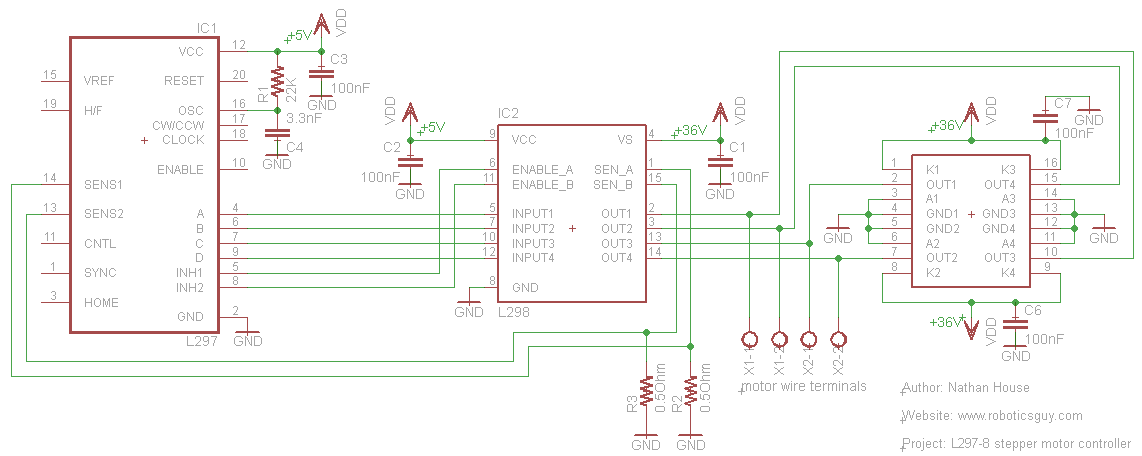
An efficient method for constructing a stepper motor controller involves creating a printed circuit board (PCB) and then placing the components onto it. Once the PCB is fabricated, the assembly and soldering of components is a quick process, especially...
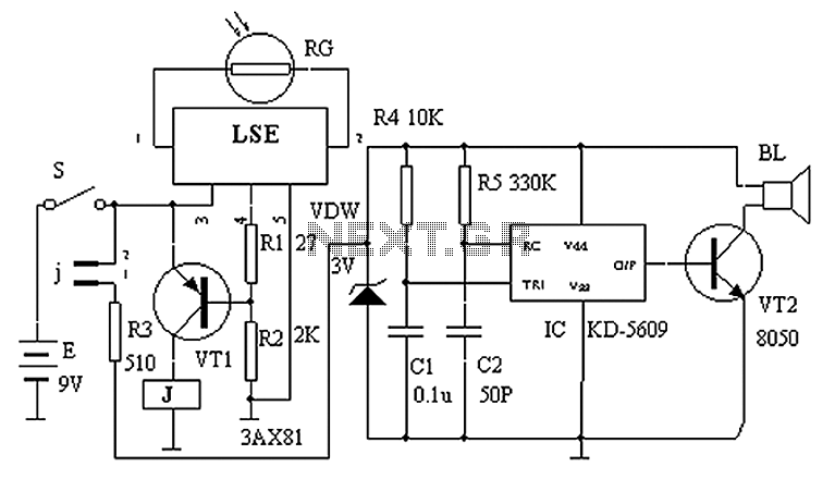
The circuit principle is illustrated in the accompanying figure. When the night light shines on the photosensitive resistor RG, it exhibits a high resistance (significantly greater than 50K). As a result, the output of the LSE pin is low,...
Listening to VHF FM offers significant advantages over MW/LW AM radio from earlier times, providing bright stereo sound free from interference, fading, and noise. However, FM radios lack the ability to predict thunderstorms as reliably as AM radios did...
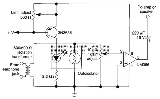
An optoisolator is utilized as an attenuator in this circuit. When the LM386 draws more current from audio signals, the 2N3638 activates, which biases the optoisolator on, thereby reducing the volume. The circuit employs an optoisolator to achieve signal attenuation,...
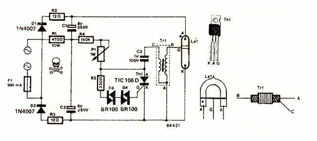
The circuit was taken from an old Elektor electronics magazine and is a compact design suitable for generating high-intensity lighting effects during festivals, parties, and gatherings. Diodes D1 and D2, along with capacitors C1 and C2, form a voltage...
The TS-440S, similar to several other radios, does not mute the microphone when utilizing the rear audio connector for digital modes. Consequently, unless the microphone is unplugged each time digital modes are used, background noise from the shack can...
Warning: include(partials/cookie-banner.php): Failed to open stream: Permission denied in /var/www/html/nextgr/view-circuit.php on line 713
Warning: include(): Failed opening 'partials/cookie-banner.php' for inclusion (include_path='.:/usr/share/php') in /var/www/html/nextgr/view-circuit.php on line 713