
PWM Waveform Capture
To capture a waveform, the Pulse Width Modulation D-to-A converter (PWM DAC) is set to its maximum output voltage. Then, using timing loops, the microcontroller looks at the voltage comparator output to determine whether the incoming voltage is higher than the PWM voltage at regularly spaced sampling times (1 microsecond in the illustration).
At each sampling time, if the incoming waveform is at a higher voltage than the PWM voltage, the PWM voltage is stored in a RAM array location corresponding to that sampling time relative to the start of the waveform. After all of the sample times have been tested against the PWM voltage, the PWM voltage is decremented and all of the sample times are compared with the PWM voltage again. This is repeated until the PWM voltage has been reduced to its minimum value, and each scan of the sample times starts by a trigger signal that is derived or in some way related to the incoming waveform.
The finer the voltage resolution, the longer the waveform capture takes. As my initial use of this is with an LCD display with 64 rows, the waveform capture circuit senses 64 different levels. To capture 100 points at 64 different levels, the total capture time is:
Capture time = 100 x [sample interval] x 64 (+ 64 X ([trigger latency]) + 68 ms,
where "trigger latency" is the average time the controller waits for the trigger edge after the last sample, and the 68 milliseconds comes from 1 millisecond settling time of the PWM circuit after each step, plus 5 milliseconds for initial settling.
When capturing waveforms with long periods, the total time needed to capture the waveform is dominated by the time it takes the waveform to make the requisite number of repetitions. For shorter periods, the total time is dominated by the settling times for the PWM. For example, for the example design to capture a waveform with 64 level resolution over a 100 microsecond interval, sampling at 1 microsecond intervals, it takes a little over 72 milliseconds. To capture a 1 second waveform at the same resolution, it takes a little over a minute.
The preceding suggests that the higher the sampling rate, the greater the possible reduction in sampling time by speeding up the DAC. A resistor network connected to some port pins could suffice for low resolution (6 bit) waveform capture. An integrated circuit DAC would probably be much better for higher resolution measurements.
The described circuit utilizes a microcontroller with integrated PWM capabilities and fast comparators to sample analog waveforms efficiently. The PWM DAC is employed to generate a variable voltage, which is compared against the incoming analog signal. The microcontroller executes a loop that samples the input signal at predetermined intervals, storing the PWM output voltage when the input exceeds this value. This process continues, reducing the PWM voltage until the minimum threshold is reached, allowing for a comprehensive representation of the waveform.
The timing calculations for capturing the waveform are crucial. The total capture time is influenced by the number of samples, the sampling interval, and the trigger latency. As the resolution increases, the time taken to capture the waveform also increases, necessitating careful consideration of the PWM's settling time and the overall system response.
For applications requiring higher resolution, the use of an integrated DAC is recommended over a simple resistor network. This allows for more precise voltage levels and faster response times, enhancing the overall performance of the waveform capture system. The design is adaptable for various applications, including audio signal processing, where accurate waveform representation is essential for subsequent filtering and analysis.The approaches using on-chip A-to-D converters on AVR, PIC, and Cypress controllers reached sample rates of up to about 60 kHz. Not really very useful for the sort of thing I was thinking about using this for: encoded data, radio control signals, A-to-D converter waveforms, checking the dynamic range of amplifiers and capturing audio waveforms for filtering and power calculations.
I realized that the comparators in AVR devices were pretty fast with a response time of several hundred nanoseconds, and that the PWM (pulse width modulation) circuit could be made fairly responsive. If there was just some way to combine these to sample analog values quickly... To capture a waveform, the Pulse Width Modulation D-to-A converter (PWM DAC) is set to its maximum output voltage. Then, using timing loops, the microcontroller looks at the voltage comparator output to determine whether the incoming voltage is higher than the PWM voltage at regularly spaced sampling times (1 microsecond in the illustration).
At each sampling time, if the incoming waveform is at a higher voltage than the PWM voltage, the PWM voltage is stored in a RAM array location corresponding to that sampling time relative to the start of the waveform. After all of the sample times have been tested against the PWM voltage , the PWM voltage is decrement and all of the sample times are compared with the PWM voltage again.
This is repeated until the PWM voltage has been reduced to its minimum value, and each scan of the sample times starts by a trigger signal that is derived or in some way related to the incoming waveform. The finer the voltage resolution, the longer the waveform capture takes. As my initial use of this is with an LCD display with 64 rows, the waveform capture circuit senses 64 different levels.
To capture 100 points at 64 different levels, the total capture time is: Capture time = 100 x [sample interval] x 64 (+ 64 X ([ trigger latency]) + 68 ms , where is " trigger latency" is the average time the controller waits for the trigger edge after the last sample, and the 68 milliseconds comes from 1 millisecond settling time of the PWM circuit after each step, plus 5 milliseconds for initial settling. When capturing waveforms with long periods, the total time needed to capture the waveform is dominated by the time it takes the waveform to make the requisite number of repetitions.
For shorter periods, the total time is dominated by the settling times for the PWM. For example, for the example design to capture a waveform with 64 level resolution over a 100 microsecond interval, sampling at 1 microsecond intervals, it takes a little over 72 milliseconds. To capture a 1 second waveform at the same resolution, it takes a little over a minute. The preceding suggests that the higher the sampling rate, the greater the possible reduction in sampling time by speeding up the DAC.
A resistor network connected to some port pins could suffice for low resolution (6 bit) waveform capture. An integrated circuit DAC would probably be much better for higher resolution measurements. 🔗 External reference
Related Circuits
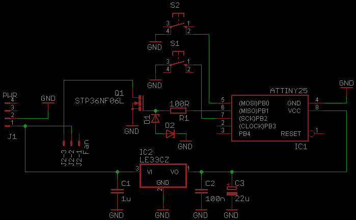
This document serves as a continuation of the previous work on PWM controllers utilizing 555 timers. The new design incorporates microcontrollers and MOSFETs in place of the 555 integrated circuits and transistors. Two versions have been developed: one equipped...
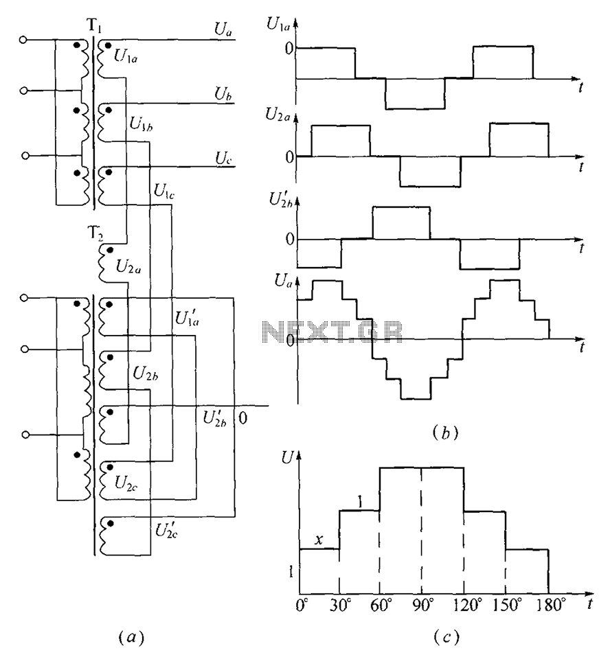
As shown, (a) for the three-phase step wave inverter output transformer winding connections; (b) in the figure, its output waveform. The three-phase step wave inverter is designed to convert direct current (DC) into a three-phase alternating current (AC) output. This...

This device is a microprocessor controlled waveform generator that can be used for driving a voltage controlled stereo panner for music applications. Panning is simply the movement of a mono audio signal between the left and right channels of...
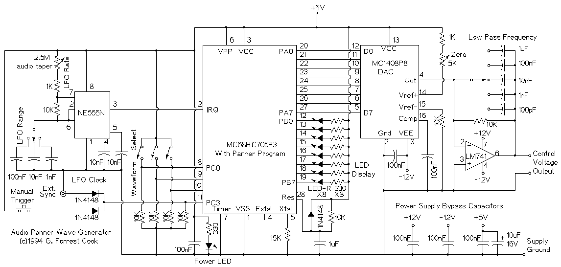
This device is a microprocessor controlled waveform generator that can be used for driving a voltage controlled stereo panner for music applications. Panning is simply the movement of a mono audio signal between the left and right channels of...
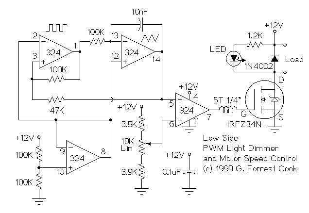
These two schematics are variations on another PWM circuit that I designed. The diagrams are for 12V operation only and there are high side (common ground) and low side (common +12V) versions. The low side version of the circuit...
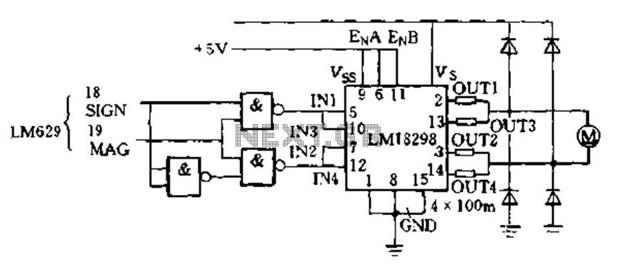
The LM629 PWM outputs directly drive the LM18298 dual H-bridge circuit, which functions as a switching amplifier. This configuration employs two H-bridges in parallel to control small DC servo motors. Additionally, the LM629 can be utilized for motion control...