
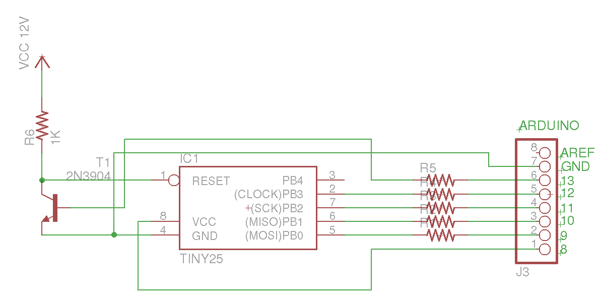
AVR microcontroller based PWM fan controllers
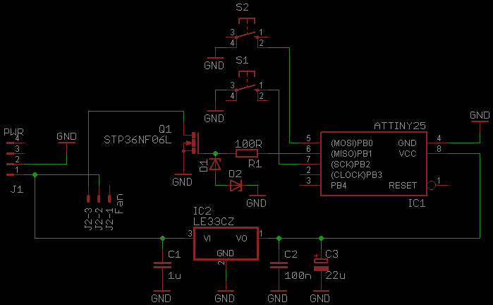
The circuit design leverages the capabilities of the ATtiny25 microcontroller, which is a compact and efficient 8-bit microcontroller from the AVR family. This microcontroller is programmed to generate Pulse Width Modulation (PWM) signals, which are essential for controlling the speed of motors or adjusting brightness in LED applications. The integration of MOSFETs allows for efficient switching and control of higher power loads compared to traditional transistors.
In the version with switches, the circuit includes two momentary push-button switches connected to digital input pins on the ATtiny25. One switch is designated for increasing the PWM duty cycle, thereby speeding up the connected load, while the other switch decreases the duty cycle, slowing down the load. The microcontroller reads the state of the switches and adjusts the PWM output accordingly.
The alternative version with a potentiometer employs an analog input pin on the ATtiny25. The potentiometer's wiper is connected to this pin, allowing the microcontroller to read the varying voltage levels as the potentiometer is adjusted. This voltage is then translated into a corresponding PWM duty cycle, providing a smooth and continuous adjustment of speed or brightness.
In both designs, the MOSFETs are used as high-side or low-side switches, depending on the application requirements. The PWM signal from the ATtiny25 drives the gate of the MOSFET, enabling it to control the power delivered to the load effectively. This configuration results in minimal heat generation compared to linear control methods, enhancing the overall efficiency of the system.
Power supply considerations for the microcontroller and MOSFETs are critical, ensuring that the voltage levels are compatible and stable. Bypass capacitors may be included near the power pins of the microcontroller to filter out any noise that could affect performance. Additionally, proper heat sinking may be necessary for the MOSFETs when operating at higher currents to prevent thermal failure.
Overall, this PWM controller design using microcontrollers and MOSFETs represents a modern and efficient approach to controlling various electronic loads, with the flexibility of user input through switches or a potentiometer.So this is a bit of a continuation on my 555 timer based PWM controllers, but now using microcontrollers and MOSFETs instead of 555 ICs and transistors. I made 2 versions, one with switches for speeding up and down and the other with a potentiometer like the previous controllers.
I used ATtiny25 controllers running at. 🔗 External reference
Related Circuits
Eight MAX6675 integrated circuits need to be connected to a microcontroller. The clock inputs can be wired in parallel. The NCS (Chip Select) lines for pairs of MAX6675 devices (1 and 2, 3 and 4, etc.) can be connected...
This circuit represents a simple transistor tester that utilizes two LEDs to indicate the condition of a transistor. It is capable of testing both PNP and NPN transistors. The core component of the circuit is the quad 2-input CMOS...
If an AC fan has three buttons (as in this case), button 1 is for low speed, button 2 is for half speed, and button 3 is for high speed. A relay can be used to switch between these...
If EAGLE is not available, a full working version can be downloaded from CadSoftUSA. A zip file containing the EAGLE schematics is provided. The EAGLE software is a widely used electronic design automation (EDA) tool that facilitates the creation of...

The circuit described is a crystal oscillation circuit using a CM OS inverting configuration, designed to ensure accurate operation. It employs a BCD counter (IC2) capable of achieving a maximum oscillation frequency of 2 MHz, which is 100 times...
This Arduino sketch is designed to recover ATtiny microcontrollers that have become non-functional due to incorrect fuse settings. It achieves this by placing the affected ATtiny into high-voltage serial programming mode and rewriting the fuses to safe values. The...
Warning: include(partials/cookie-banner.php): Failed to open stream: Permission denied in /var/www/html/nextgr/view-circuit.php on line 713
Warning: include(): Failed opening 'partials/cookie-banner.php' for inclusion (include_path='.:/usr/share/php') in /var/www/html/nextgr/view-circuit.php on line 713