
Quartz Controlled Bedroom Light Switch

The automatic light switch circuit operates using a photoresistor (LDR) and a transistor as the primary components. The circuit is designed to turn on the light automatically when ambient light levels fall below a certain threshold, making it ideal for nighttime use in bedrooms.
The LDR is connected in a voltage divider configuration with a fixed resistor. As the ambient light decreases, the resistance of the LDR increases, causing the voltage at the junction of the LDR and the resistor to rise. This change in voltage is used to control the base of a transistor, which acts as a switch.
When the voltage at the base of the transistor exceeds a certain level, the transistor enters saturation and allows current to flow from the collector to the emitter. This current can then be used to energize a relay or directly drive the light fixture, depending on the specifications of the components used.
The circuit should be powered by a suitable voltage source, ensuring that all components are rated for the voltage in use. Additionally, it is advisable to include a diode in parallel with the relay coil to prevent back EMF from damaging the transistor when the relay is de-energized.
This design offers a straightforward solution for automatic lighting control, enhancing convenience and energy efficiency in bedroom environments. Proper component selection and layout are crucial to ensure reliable operation and safety.Here is an ultra simple automatic light switch circuit for bedrooms. After construction,connect the input terminals of this circuit in parallel to the inte. 🔗 External reference
Related Circuits
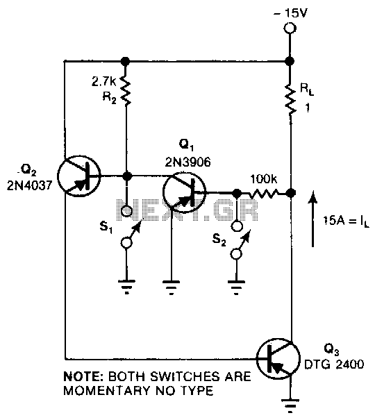
This circuit provides the turn-on characteristics of a Silicon Controlled Rectifier (SCR) but allows for easy turn-off. The switch consists of three transistors with decreasing current ratings: Q3 has a high current rating, while Q2 has a medium rating....
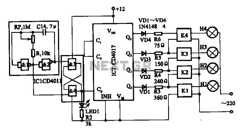
This circuit illustrates a circular lighting control system. It consists of four two-input NAND gates from the CD4011 series, which form a non-inverting multivibrator. This multivibrator generates a pulse that is used to shape the output of an RS...
This application note outlines the functionality of the MAX4929E, which manages the switching of all low-frequency signals (LoF) required for a 2:1 HDMI/DVI switch while providing high-level ESD protection for all external lines. It also details how the MAX4929E...
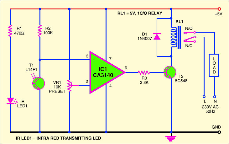
The circuit described here operates without physical contact to control the appliance. It requires the user to move their hand between the infrared LED (IR LED1) and the phototransistor (T1). The infrared rays emitted by IR LED1 are detected...
This circuit is a differential analog switch circuit utilizing the FM1208 monolithic dual differential multiplexer. It is designed for applications where the on-resistance (RDS(ON)) must match closely. The RDS(ON) for the monolithic dual multiplexer exhibits better than 1% accuracy...
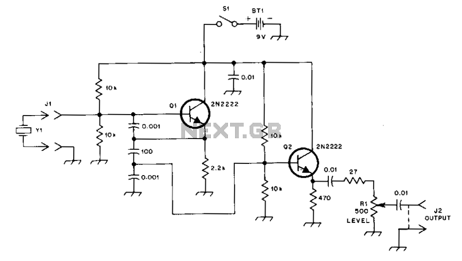
This general-purpose signal source is highly effective for signal-tracing applications. The output level is adjustable, exceeding 1 Vrms into a 50 Ω load. It is compatible with nearly any crystal in the 1 to 15 MHz frequency range. Q1...
Warning: include(partials/cookie-banner.php): Failed to open stream: Permission denied in /var/www/html/nextgr/view-circuit.php on line 713
Warning: include(): Failed opening 'partials/cookie-banner.php' for inclusion (include_path='.:/usr/share/php') in /var/www/html/nextgr/view-circuit.php on line 713