
Quick move LED game

The Quick Draw circuit is designed to test and compare the reaction times of two participants in a competitive format. The circuit consists of a referee switch (S1), two player switches (S2 and S3), and two indicator LEDs (LED1 and LED2).
When the referee presses S1, it activates LED1, signaling the start of the duel. This LED serves as a visual cue for both players to react. Each player has a switch that they must press to indicate they have drawn. S2 is designated for Player 1, while S3 is for Player 2. The switches are typically momentary push-button types that return to their original position when released.
The circuit employs a microcontroller or a combination of logic gates to monitor the state of the switches and control the LEDs. When S1 is pressed, the microcontroller initiates a timer and waits for either S2 or S3 to be pressed. The first switch to be activated will trigger the corresponding LED to light up.
To ensure that only one LED lights up, the circuit is designed with a latch mechanism. This mechanism prevents the second LED from lighting once one player has drawn. In practical terms, this can be achieved using a flip-flop circuit or a simple logic gate arrangement that disables the other player's switch once one has been activated.
The design should also incorporate debounce circuitry to avoid false triggering due to mechanical bounce when the switches are pressed. Capacitors and resistors can be used to smooth out the signal from the switches, ensuring reliable operation.
Power supply considerations are also important; the circuit can be powered by batteries or a DC power source, with appropriate voltage regulation to ensure safe operation of the LEDs and microcontroller.
In summary, the Quick Draw circuit combines simple electronic components to create an engaging game of reflexes, providing a clear indication of the winner through visual feedback while ensuring robust performance through careful design considerations.The object of Quick Draw is to test your reaction time against your opponent's. A third person acts as a referee and begins the duel by pressing S1, which lights LED1. Upon seeing LED1 go on, you try to outdraw your opponent by moving S2 from "Holster" position to "Draw" position before your opponent moves S3 from "Holster" to "Draw" position. Who ever gets there first will light the corresponding LED and will automatically prevent the other LED from lighting, clearly indicating a winner.
🔗 External reference
Related Circuits
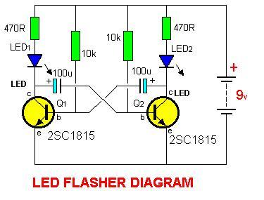
2SC1815 Flip Flop LED Flasher is a very simple and easy-to-understand circuit. The 2SC1815 Flip Flop LED Flasher circuit utilizes a 2SC1815 transistor, which is a general-purpose NPN transistor, to create a basic LED flasher. This circuit operates on the...
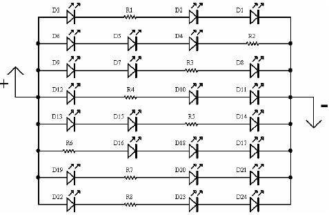
A light-emitting diode (LED) lamp is a solid-state lighting device that utilizes light-emitting diodes as its light source. LEDs are a cost-effective and convenient choice for various lighting applications. They are available in an extensive range of colors, styles,...
The OPB350 series liquid sensor is designed to operate with clear tubes of various outer diameters: 1/16 inch (1.6 mm), 1/8 inch (3.2 mm), 3/16 inch (4.8 mm), and 1/4 inch (6.3 mm). When integrated with output reference circuitry,...

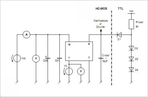
A voltage-controlled oscillator using the NE555. This circuit is commonly referred to as a voltage-to-frequency converter because the output frequency is altered by varying the input voltage. As previously noted, pin 5 serves as the voltage control terminal, which...
This is a classic 2-transistor astable multivibrator. Many other NPN small signal or switching transistors can be used, including 2N4401, PN2222, or 2N2222 using the circuit on the left. The circuit can also be inverted using PNP transistors such...
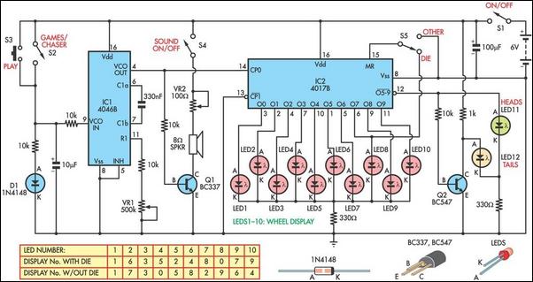
This circuit functions as a light chaser and can be configured to simulate either a heads or tails game (Two Up) or a dice game. It incorporates a speaker to replicate the sound of a spinning roulette wheel. The...