
R/C Timer-Switch for Radio Control Applications
The heart of the circuit is the popular CMOS Timer IC, 7555. When power is applied from the battery, the IC`s output pin 3 is switched `OFF` (0V) and a short circuit applied to C5, thus ensuring it is completely discharged. When a momentary start signal is applied to pin 2, the output immediately switches `ON` (+V), thus switching on the MOSFETs and the motor via the soft start circuit R4, D1 and C6 (if fitted).
This latter circuit slows down the switching on of the MOSFETs, giving a more gradual increase in current to the motor. If soft start is not required, omit these components and wire pin 3 directly to the MOSFET gate terminals G.
When the voltage across C5 reaches 2/3V, the IC detects this and its output switches `OFF`, thus immediately switching the MOSFETs and the motor off via D1. The 7555 timer IC also re-applies the short across C5 and the circuit returns to its initial condition ready for the next motor run.
Zener diode D2 provides protection to the MOSFETs from the high frequency transients that all DC motors generate, but do not omit the normal spark suppression capacitors C3 and C4 wired directly from the motor terminals to its case (0. 1uF ceramic disc types are fine). R3 = 390K R4 = 1M P1 = 1M, trimmer C1, C2, C3, C4 = 0. 1uF (100nF) C5 = 47uF/10V, low-leakage electrolytic C6 = (optional) D1 = 1N4148, 1N914, or equivalent ZD1 = Zener Diode, 30V IC1 = 7555 CMOS Timer Q1, Q2 = BUZ11 MOSFET, or equivalent S1 = on-off-on switch (see text) Fuse = 7.
5A C1 to C4 are of the ceramic 50V types. C5 has to be a low-leakage type like tantalum or something. C6 an is optional electrolytic type and no exact value is specified; it depends on the `Soft-Start` part of the circuit and quantity of MOSFETs you stack in parallel. Start with 22 µF and increase the value if needed. S1 is a special toggle switch which locks on one-side to prevent accidental injury by flipping the switch to the `start` position when you`re not ready yet.
Or fabricate some sort of `power-disable` thingy if you are unable to obtain this switch. The switch should be the on-center-on type. Q1 & Q2 are BUZ11, N-channel, Power, HiSpeed Switch, TMOS Fets, each at about 25A each. Substitutes are fine as long as you keep the rDS switch-on resistance of 0. 05 ohms or less in mind or you may find that the circuit will switch on fine but does not switch off after the pre-determined time you have set it for with trimmer pot P1. For example, the IRFZ30, IRFZ32, IRFZ40, or IRFZ42 are good choices with an rDS(on) of 0. 05, 0. 08, 0. 028, and 0. 035 ohms. These type mosfets have a so-called `Power Enhancement Mode` feature. Especially the IRFZ40/IRFZ42 are 46/51Amps which probably allows you to get away with one mosfet only.
They are however a bit more expensive. R4, D1, and C6 are optional for a soft start. If you don`t require the soft-start then leave them out. C3 & C4 are wired straight across the motor terminals for spark suppression which every electric motor generates. Not needed of course (but does no harm) if you use a brushless motor. The 30V zener diode D2 is to protect the mosfets from transients. Your choice of substitutes for Q1 and Q2, if you can`t find the BUZ11, has to switch comfortably 6 amps e
🔗 External reference
Related Circuits
An RF field indicator is needed to verify power stages and transmitter antennas. This radio field indicator allows for the measurement of radiated energy from antennas. An RF field indicator is a crucial device in the field of telecommunications and...
The circuit utilizes two white LEDs, with the second LED connected across the emitter of the transistor and the negative ground. It requires its own limiting resistor in series, similar to R15 and D3 in the circuit diagram. If...
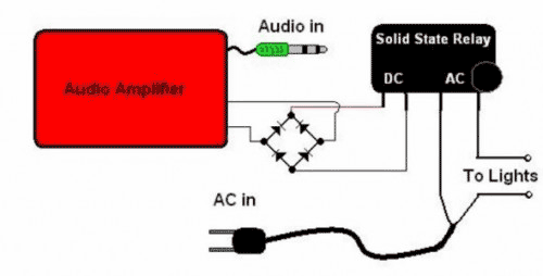
The basic Idea was to have Christmas lights flash with the music. In my design I use an ordinary amplified computer speaker, a diode bridge, and a ‘CRYDOM’ SSR (Solid State Relay). In order to increase the time that...

The fan used is a new electrostatic type, known for its reliability due to the absence of wearing parts. These devices require a high-voltage drive. When power is applied, the thermistor located in the fan's exhaust stream has a...
The ADM1066 from ADI Company is a monitoring device designed to manage various configurable sequencing applications. It features 12 ADCs and 6 8-bit DACs with a voltage output precision exceeding 0.5% at 25 degrees Celsius. This device is primarily...
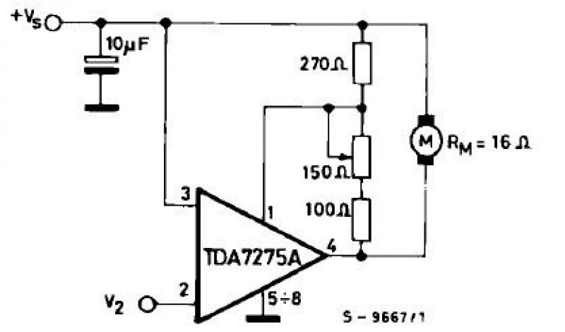
The TDA7275A linear integrated circuit, housed in a minidip plastic package, can be utilized to design a straightforward speed regulator electronic project suitable for regulating the speed of small DC motors. The TDA7275A DC speed controller project is specifically...
Warning: include(partials/cookie-banner.php): Failed to open stream: Permission denied in /var/www/html/nextgr/view-circuit.php on line 713
Warning: include(): Failed opening 'partials/cookie-banner.php' for inclusion (include_path='.:/usr/share/php') in /var/www/html/nextgr/view-circuit.php on line 713