
Fine Control Super Bright LED Pulser

The circuit design incorporates two white LEDs, where the second LED is positioned across the emitter of a transistor. This configuration ensures that the LED operates effectively while being grounded to the negative voltage. A limiting resistor must be included in series with this LED to prevent excessive current flow, mirroring the arrangement of R15 and D3 as depicted in the schematic.
In instances where red, yellow, or green LEDs are preferred, it is recommended to connect two of these LEDs in series. This series connection is essential to achieve a voltage drop similar to that of a single white or blue LED, ensuring consistent brightness and performance across different LED colors.
For the integrated circuits (ICs) utilized in this circuit, it is crucial to manage the unused sections correctly. These sections should have their inputs connected to negative ground, while the outputs must be left unconnected. This practice prevents potential interference and ensures the stability of the circuit’s operation, as illustrated in the lower part of the schematic diagram.
The timing characteristics of the circuit can be modified by adjusting the capacitance values of C3 and C4. Replacing these capacitors with units rated at 47 µF 25V or higher will extend the time delays, allowing for greater flexibility in timing applications. However, it is imperative to only vary the values of these capacitors, as the resistor values connected to the four control pots are critical to the circuit's performance and should remain fixed to maintain the intended functionality.Wanting to use two white LEDs, the second device must be wired across the Emitter of the transistor and negative ground with its own limiting resistor wired in series, like R15 and D3 in the circuit diagram. If common red, yellow or green LEDs are required, please wire two of them in series, in order to present roughly the same voltage drop of one
white or blue LED. Please note that the unused sections in both ICs must have their inputs tied to negative ground whereas the outputs must be left open, as shown at the bottom of the diagram. All time-delays can be increased by changing the value of C3 and C4 to 47 µF 25V or even higher. Please vary the value of these capacitors only, as the values of the resistors wired to the four control pots are rather critical and should not be changed.
🔗 External reference
Related Circuits
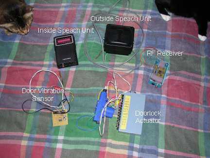
Our present car controller runs on a single PIC16F870 micro and provides functions for remote door locks, headlight reminder, and car finder. It is constructed using wire-wrap to allow for future expansion and is mounted using Velcro on the...
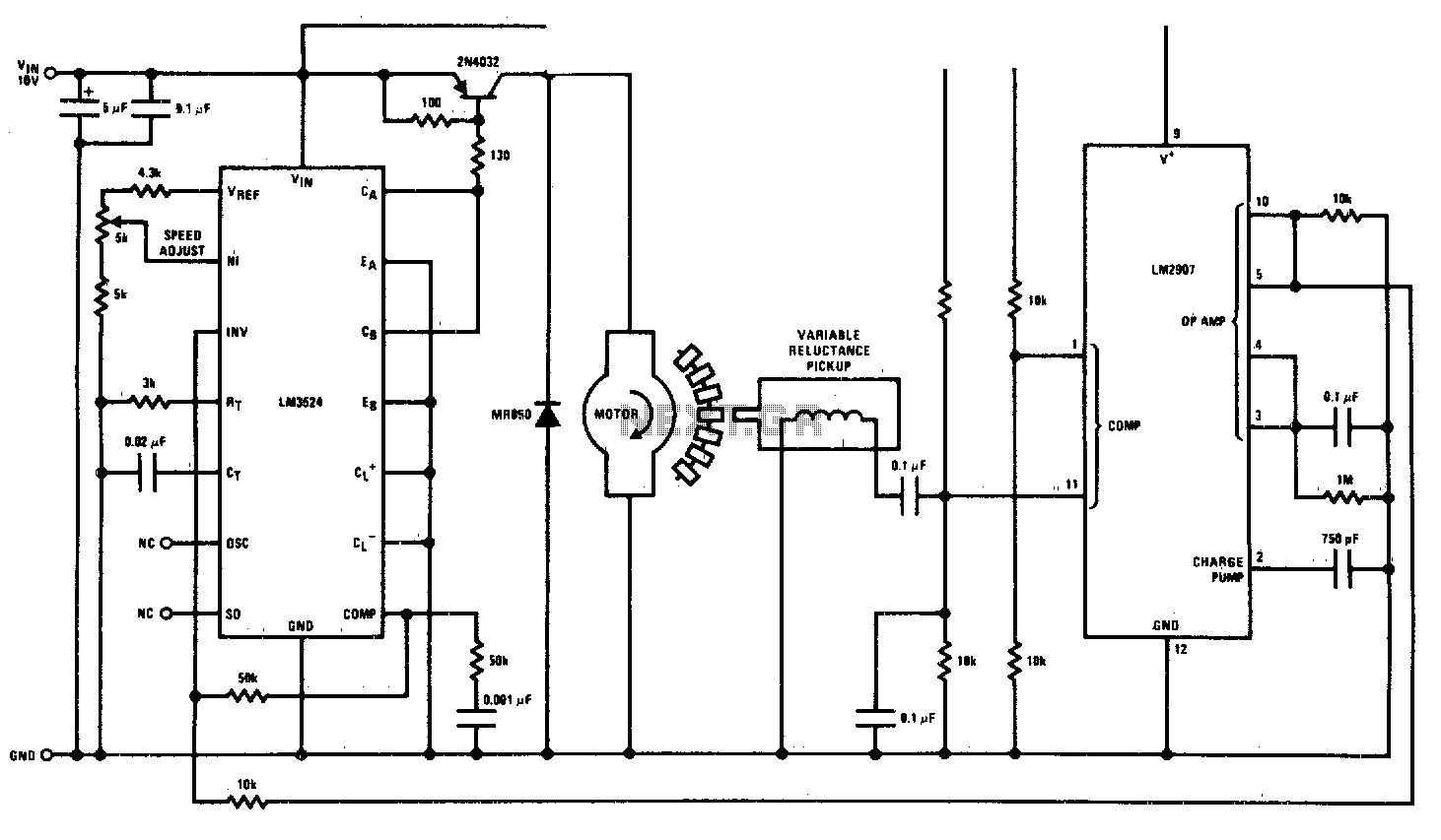
This circuit is a regulating series DC motor speed control using the LM3524 for the control and drive of the motor and the LM2907 as a speed sensor for the feedback network. The circuit employs the LM3524 integrated circuit, which...
This circuit enables the switching on and off of appliances through telephone lines. It allows for the control of appliances from any distance, overcoming the limitations of infrared and radio remote controls. The circuit can manage up to nine...
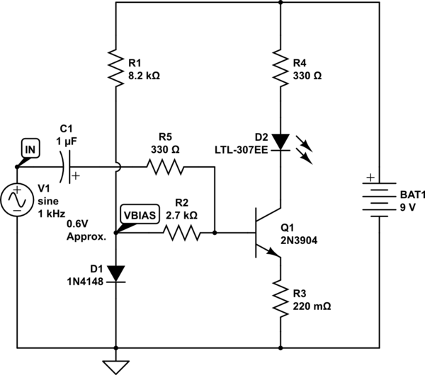
The goal is to take the voltage output from a 3.5mm audio jack and use it to light up an LED based on the audio voltage levels. The left audio channel will be connected to the base of a...
A microphone cannot be directly connected to a power amplifier because the signal is too weak. Standard audio power amplifiers accept about 1 Vrms to provide a full output. To effectively interface a microphone with a power amplifier, an intermediary...
The consumer unit cupboard in some older houses is poorly illuminated. If a bell transformer is also situated in this cupboard, it can be utilized to provide emergency lighting using two high-current LEDs. These diodes are powered through a...