
Rainwater Storage Gauge
The circuit design for rainwater level monitoring and pump protection integrates several key components that function cohesively to provide reliable operation. The voltage divider circuit is critical, as it translates the physical state of the water level into an electrical signal. The float switches, which are strategically placed at different heights, serve as sensors that trigger changes in the voltage divider output as the water level fluctuates. Each switch is designed to close at a specific water level, effectively shorting out its associated resistor, thus altering the voltage seen at the output.
The op-amps configured as comparators compare the output voltage from the divider with reference voltages set by the R7 to R12 resistor chain. This configuration allows for precise detection of the water level, enabling the corresponding LED indicators to illuminate accurately. The design's scalability is a significant advantage, allowing for the addition of more float switches and the expansion of the voltage divider chain to enhance the resolution of the water level readings.
In terms of power management, the circuit is designed to operate efficiently with a maximum current draw of less than 25mA, which is suitable for battery-operated systems or applications where power conservation is essential. The use of non-standard resistor values can be easily addressed by combining standard resistor values, ensuring that the design remains cost-effective and accessible for DIY implementations.
Furthermore, the pump protection feature is a critical safety addition. By utilizing the SSR1 relay, the circuit can effectively disconnect the pump from the mains supply when the tank approaches empty, thus safeguarding the pump from damage due to dry operation. The high isolation voltage provided by the SSR ensures that there is adequate safety between the low-voltage control circuit and the high-voltage mains supply, which is especially important in installations near water.
Overall, this rainwater collection and monitoring system not only promotes sustainable practices but also incorporates essential safety and operational features that enhance its practicality for domestic use.Not only on ecologically grounds but also economically it makes sense to collect rainwater for use in the garden and increasingly for `grey water` domestic use. People who take rainwater collection seriously use large underground tanks for storage. The problem now arises, how can the water level be determined without lifting the tank hatch and pee ring in One solution is to use float switches mounted at different heights in the water tank, and to use a row of LEDs mounted remotely to show the water level in the tank. Transferring this information to a remote display will involve long cable runs so it is of interest to reduce the number of cables to a minimum.
The circuit here shows how information about the water level in a tank can be sent over two wires to a remote LED display. R1 together with the resistor chain made up of R2-R6 form a voltage divider,‚oat switches are wired across the resistors R2-R6 in one arm of the voltage divider.
As water flows into the tank and the level rises, switch S5 closes followed by S4, etc. Each time a switch closes, it will short out its parallel resistor in the chain thereby changing the output voltage of the divider. When the tank is full, allve switches will be closed and all the LEDs will be on. The voltage output from this divider chain is applied to the inputs of five op amps that are configured as comparators.
A voltage chain comprising R7-R12 supplies the reference voltage for each of the five comparators. Both divider chains use the same supply so they will be insensitive to supply‚uctuations. The maximum supply current for the circuit is less than 25mA. Some of the resistors chosen to make up the voltage dividers are not standard values but can be easily made up from combinations of 10k and 100k resistors. If you need to expand thisve level display to give a better resolution of the tank contents, it is a simple job to add more float switches and to expand the voltage divider chain.
IC2 also has three spare op amps; these can be pressed into service as further comparators. Underground tanks inevitably require a pump to move the water to where it will be used. An optional feature of this design is the pump protection circuit. When LED D1 goes off indicating that the tank is almost empty, the solid state relay SSR1 can be used to switch off the mains power to the pump. This will prevent damage to the pump when the tank runs dry. The S202 SE1 solid-state relay (SSR) from Sharp has an isolation voltage between its input and output of 3000V (Class 1).
It is important to note here that any mains equipment near the water tank installation must be supplied from an RCD safety socket for the sake of your own health! 🔗 External reference
Related Circuits
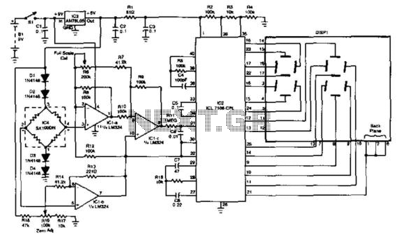
This gauge utilizes an Intersil ICL 7106 A/D converter chip along with an LED display module. It incorporates a Sensym Corp. pressure transducer SX100pn (100 psi full scale) arranged in a Wheatstone bridge configuration, which drives an operational amplifier...
The Car Temperature Gauge is fundamentally similar to March's project, with some minor modifications to the input circuit. This circuit will display the water temperature with a resolution of 1 degree. The Car Temperature Gauge circuit is designed to accurately...
A digital storage oscilloscope (DSO) is a very important piece of test equipment that can do the jobs that a normal CRO just can't handle. Such as capturing single shot and widely spaced waveshapes, and looking at non-repetitive signals...
While driving the car, the gauges turn off and the car stalls immediately. The car will not start until the gauges come back on. When the gauges are off, the car starter will turn over the engine, but it...
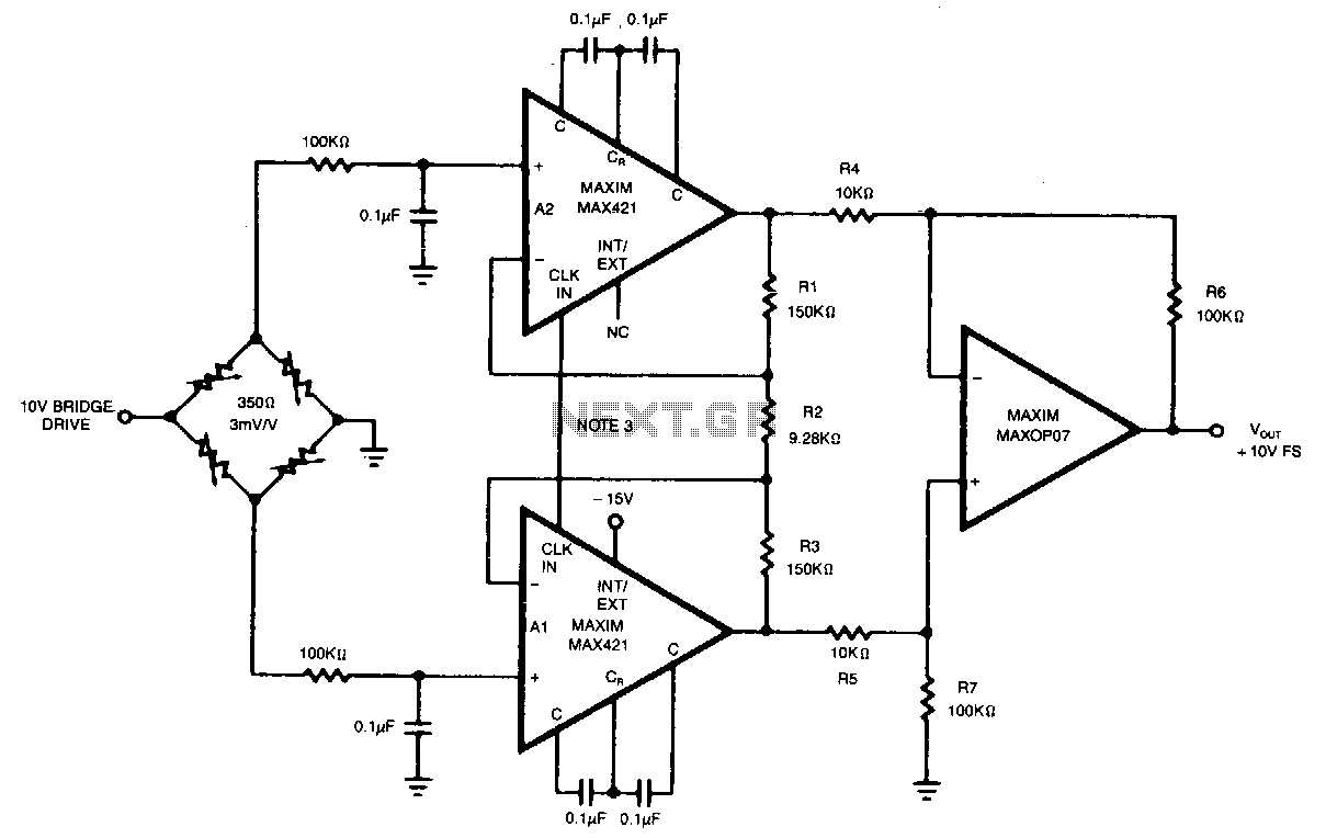
This circuit achieves an overall gain of 320. Additional gain can be obtained by decreasing the value of R2. The untrimmed Vas is 10.11V, and the Vas temperature coefficient is less than 0.1µV/°C. In various applications, the OP07 can...
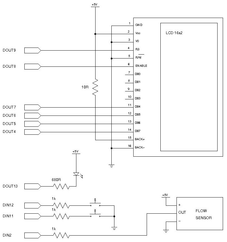
Measuring the consumption of a resource that has units by volume can be more challenging than it appears. Resources such as water, gas, and electricity are typically measured using gauges that determine either the instantaneous flow rate or the...