
Ramp generator

The 566 integrated circuit (IC) serves as a versatile ramp generator, capable of producing linear voltage ramps in both positive and negative directions. The positive ramp generator configuration utilizes an external transistor connected to Pin 3, which acts as a discharge switch for capacitor C1. When the voltage across C1 reaches a predetermined threshold, the transistor rapidly discharges C1, enabling the charging cycle to initiate again without delay. This rapid discharge mechanism is crucial for maintaining the frequency stability of the output waveform.
In the negative ramp generator configuration, the process is reversed. The pnp transistor is employed to charge the timing capacitor C1 swiftly at the end of the discharge cycle, ensuring that the ramp generation process is efficient and responsive. This design allows for precise control over the ramp characteristics and ensures minimal drift over temperature variations, thereby enhancing the reliability of the circuit in various applications.
The operational frequency of the 566 ramp generator is determined by the external components connected to it. The free-running frequency f0 is influenced by the bias voltage Vc at Pin 5 and the total resistance RT between Pin 6 and the positive supply voltage Vcc. By adjusting these parameters, the user can tailor the frequency and duty cycle of the output waveform to meet the specific requirements of the application.
Moreover, the availability of a short pulse at Pin 3 provides additional functionality. This pulse can be utilized in timing applications or as a trigger signal for other circuits. To modify the characteristics of this pulse, a collector resistance can be added in series with the external transistor collector, which will extend the pulse duration, allowing for more versatile applications in timing and control systems. The design of the 566 ramp generator, therefore, offers significant flexibility and precision, making it suitable for a wide range of electronic applications.The 566 can be wired as a positive or negative ramp generator. In the positive ramp generator, the external transistor driven by the Pin 3 output rapidly discharges Cl at the end of the charging period so that charging can resume instantaneously. The pnp transistor of the negative ramp generator likewise rapidly charges the timing capacitor Cl at the end of the discharge period.
Because the circuits are reset so quickly, the temperature stability of the ramp generator is excellent. The period where f0 is the 566 free-running frequency in normal operation. Therefore, where Vc is the bias voltage at Pin 5 and RT is the total resistance between Pin 6 and Vcc. Note that a short pulse is available at Pin 3. (Placing collector resistance in series with the external transistor collector will lengthen the pulse.)
Related Circuits
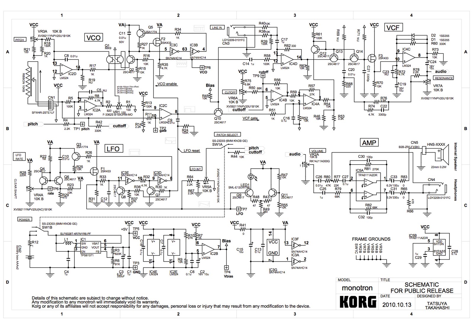
A voltage-controlled oscillator (VCO) using the LM324 operational amplifier is being developed, inspired by the Korg Monotron schematic. The goal is to create a simple circuit that produces audible waveforms, specifically square and triangle waves, when connected to a...
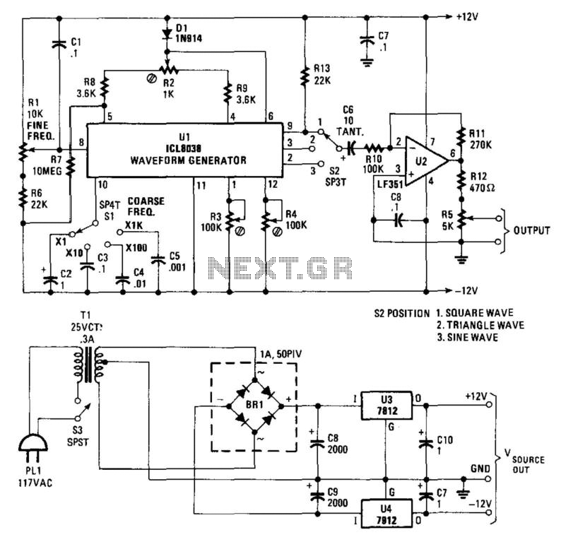
Using an Intersil ICL8038, this function generator produces frequencies ranging from 1 Hz to over 80 kHz. R1 is the fine frequency control, while S1 is the coarse frequency control range switch. S2 selects the output waveform as square,...
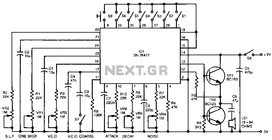
Six preset controls and seven selector switches enable a vast range of different sounds to be produced and altered at will. Such sounds as steam trains chuffing, helicopters flying, bird chirping, and machine guns firing are possible, as well...
This simple circuit generates a good and stable 1V peak-to-peak square wave at 100Hz, 1KHz and 10KHz using a single 1.5V cell as power supply. An useful feature of this circuit is that frequency changes can be obtained by...
If the ramp driving your PWM-based controller is not linear, monotonic, or is simply noisy, your DC/DC converter will not perform optimally. It is essential to understand how to achieve the best performance from your system. A typical DC/DC...
A rectangular-wave pulse generator with an extremely long period can be constructed using only two components: a National Semiconductor LM3710 supervisor integrated circuit (IC) and a 100-nF capacitor to suppress noise spikes. This circuit leverages the watchdog and reset...