
Simple Square wave Generator
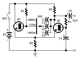
The described circuit utilizes a single 1.5V power supply to generate a square wave output, which can be adjusted to three distinct frequencies: 100Hz, 1KHz, and 10KHz. The circuit operates efficiently, drawing a current of approximately 600µA.
The core component of this circuit is likely a 555 timer IC configured in astable mode, which is a common approach for generating square waves. The frequency of oscillation in such a configuration is determined by two resistors and a capacitor. In this case, the design allows for easy frequency adjustments by swapping out just one capacitor, which simplifies the process of tuning the circuit for different applications.
The square wave output is specified to have a peak-to-peak voltage of 1V, which indicates that the circuit is designed to operate within low voltage levels, making it suitable for battery-powered applications. The stability of the output waveform is crucial for various applications, including clock signals in digital circuits, timing applications, and audio signal generation.
The choice of using a single capacitor for frequency adjustment is an efficient design feature, as it minimizes the number of components that need to be changed for different frequency outputs. This modular approach allows for quick reconfiguration of the circuit without extensive modifications.
Overall, this circuit exemplifies a straightforward and effective method for generating low-frequency square wave signals with minimal power consumption, making it suitable for educational purposes, prototyping, and low-power applications.This simple circuit generates a good and stable 1V peak-to-peak square wave at 100Hz, 1KHz and 10KHz using a single 1.5V cell as power supply. An useful feature of this circuit is that frequency changes can be obtained by switching only one capacitor at a time.
Current consumption is about 600µA. 🔗 External reference
Related Circuits
The apparatus consists of a cavers point detection circuit and a triggering display circuit. The cavers instrument functions as a test probe, which, when held in one hand, can detect acupuncture points by touching the skin with another probe....
The hex switches are connected to J2 as follows: pin 1 is the common of both switches (+5V), pin 2 is the least significant bit (LSB) up to pin 5 which is the most significant bit (MSB) of the...
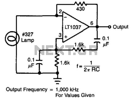
In this circuit, the Wien bridge network provides phase shift, and the lamp regulates the amplitude of the oscillations. The smooth, limiting nature of the lamp's operation, in combination with its simplicity, yields good results. Harmonic distortion is below...
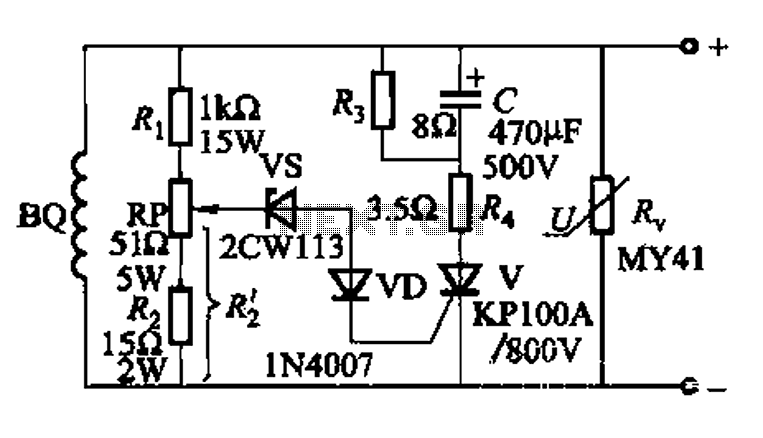
The DC voltage for the generator field winding is supplied by a three-phase thyristor rectifier. In instances of incorrect operation, phase misalignment, or system failure, the rectifier may generate hazardous conditions, leading to over-voltage insulation issues on the DC...
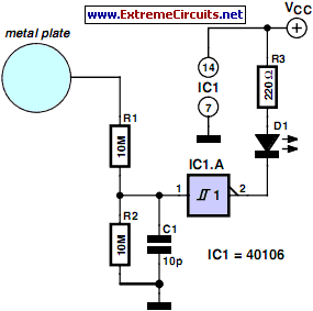
This simple circuit can be used to activate various devices, such as microcontrollers, relays, secret alarms, or even to turn on LED1, which illuminates as long as a metal plate is touched. The circuit consists of a voltage divider...
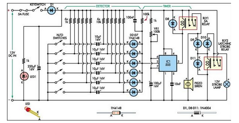
This simple alarm circuit was designed for use in a combined garage and rumpus room. It can be assembled on Veroboard and uses just one IC plus a handful of additional components. The alarm circuit is based on a single...