
RCA CT-100 Color Television Design
You might be a little surprised to hear that the CT-100 contains solid-state components. It actually uses five of them: two selenium rectifiers for the low-voltage power supply and three crystal diodes for the RF mixer, audio detector, and video detector. My 1940s televisions use tubes for all of those functions. Had the CT-100 followed suit, its tube-count would have topped forty! The CT-100`s 15GP22 picture tube is both rare and complex. Few were produced in the first place, and of the few survivors, many have lost vacuum, relegating them to the netherworld of duds.
It is not possible to substitute any other tube without making modifications that would destroy the authenticity of the CT-100. The 15GP22 had a short service life, and at this writing (November, 2010) nobody in the world has a commercial process for rebuilding it.
Here`s a page from its data sheet : In many picture tubes, the envelope is a single glass piece, like a light bulb. In the 15GP22, the face and the body are separate glass pieces bonded to a metal flange, or ultor ring.
This picture shows the two glass parts with metal rings attached: Beams from the CRT`s electron guns pass through holes in the shadow mask and strike phosphor dots on the glass plate, illuminating them. High precision was needed to fabricate these parts and mount them in alignment. Metal and glass have different expansion coefficients, and the manufacture process took special care with heating and cooling cycles to avoid (among other things) breaking the glass phospor-dot plate held in its metal frame.
Many details of the 15GP22 manufacturing process are given in the article Improvements in the RCA Three-Beam Shadow-Mask Color Kinescope, from the January, 1954 issue of I. R. E. Proceedings. The two previous photos appear in that article. Many picture tubes can easily be rebuilt by substituting a new electron gun assembly. This is not true for the 15GP22, and the unavailability of rebuilding makes every good 15GP22 even more valuable.
The Achilles` heel of the tube is the double glass-to-metal bond between the flange rings and glass envelope parts. If that bond fails anywhere, air leaks into the tube and ruins it. Further, the two metal flange parts are machine-welded together around their perimeters, and the weld is another potential source of leaks.
For more than ten years, dedicated TV restorers including John Folsom and Bob Galanter worked to develop a process for rebuilding a 15GP22 tube. Late in 2009, the team announced their first successful rebuild ”a real achievement. In early 2010, they had a setback when two candidate tubes failed during a rebuild trial. Each tube failed in a different way. One lost vacuum after their best attempts to seal it. Another suffered a cracked stem in the oven. The team suspended their project pending further research. Also during 2009-2010, Jerome Halphen in Paris consulted with the French company RACS and brought them a candidate tube for rebuilding.
After coating a leaky area with frit glass, RACS rebuilt the tube and it was demonstrated at the 2010 Early Television Foundation convention. Although very encouraging, the RACS process is still in the experimental stage as of November, 2010. Another little surprise is that the CT-100 can receive UHF (ultra-high frequency) as well as VHF broadcasts.
UHF broadcasting was not widespread in 1954, but it did exist. The CT-100`s turret-style tuner has sixteen positions. Each position could be set to receive a VHF channel (2-13) or UHF channel (14-83). For a new CT-100, the dealer would set it up to receive the channels in that locality. Mechanically, this was done by inserting a "channel strip" for each desired channel in the tuner. A drawing from RCA patent 2, 643, 361 shows a tuner of this general type. The strips (Fig. 3) can be popped in and out of the rotating turret assembly. The photo shows strips in the CT-100 tuner. The channel indicator came from the factory showing the standard twelve VHF channels plus four UHF positions. My CT-100 was set up for VHF channels 2-13 plus UHF channels 14, 16, and 18. My restoration article has more about this indicator. Many early sets such as my National TV-7W had tuners that selected fewer than twelve VHF channels. Although the VHF band included channels 2-13, the FCC limited the number of stations in any given locale to a maximum of eight.
It put further limits on adjacent channels to minimize interference. In practice, the biggest US cities such as New York might have six or seven VHF channels; smaller cities and towns had fewer. UHF broadcasting was even more limited because that market was poorly developed. In 1954, a major city might have a couple of UHF stations, but vast areas of the USA had none. All-channel UHF tuners were almost unheard-of in the 1950s. They did not become common until 1965, when the FCC forced manufacturers to put them in every new TV.
With sixteen possible channels, the CT-100 tuner was adequate for 1954. Its only drawback was that if you moved to a new town, you might need to have the dealer adjust the tuner to different channels. In the library below, you`ll find a detailed article, A VHF-UHF Television Turret Tuner. Written by RCA engineers, it analyzes all of the tuner circuits and gives the results of extensive field testing.
The CT-100 has one gizmo, the "field neutralization coil, " that I haven`t seen on other TVs. It is a simple coil that goes around the front of the picture tube and is controlled by an adjuster on the back of the low-voltage power supply cabinet. At first glance, I mistook this for a built-in manual degausser. Newer color TVs have a built-in automatic degausser, also a simple coil around the CRT face, which briefly energizes each time you turn on the TV.
This lets you move the TV in your house without having to manually degauss the set to counteract the change of position within Earth`s magnetic field. The field neutralization coil is actually used to adjust purity around the CRT edges when you are going through setup routines.
You can read more about purity adjustments and the field neutralization coil in my restoration article. DC restoration affects the TV`s ability to maintain correct black levels in scenes with high contrast.
Better-quality black and white TVs like my DuMont RA-103 have a separate DC restoration circuit, but cheaper sets do not. In a TV without DC restoration, if you set the brightness and contrast for good black levels in bright scenes with high contrast, the overall picture may be too dark in darker scenes with high contrast.
The CT-100 has a separate stage of DC restoration for the Red, Green, and Blue signals produced in the TV`s color matrix/output section. Later color TVs such as my 1961 CTC-11 omit this stage. Several sections of the CT-100 are pretty conventional for the mid-1950s and will not be discussed here.
These include the power supplies (low and high voltage), RF and IF amplifiers, and horizontal and vertical sweep. You can find details about those sections in the technical library below, particularly the RCA service manual and Grob`s description of the CT-100.
Some people ask whether the CT-100 resembles a prototype, slapped together in a hurry. The answer is No. The CTC-2 chassis clearly evolved from earlier proven designs, such as the much-imitated 630TS. You can also trace a clear evolution from this to subsequent RCA color chassis: the CTC-3, CTC-4, and so forth. In some ways, a later chassis like my CTC-11 was a dumbing-down of this design, cheaper to build and simpler to service, with no DC restoration, three video IF stages rather than five, X-Y rather than I-Q demodulation, and a wafer tuner rather than a turret.
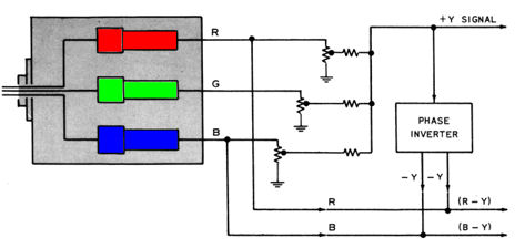
It`s hard to fault RCA for economizing when their color TV cost as much as a new car. I have heard that no manufacturer made money from color until well into the 1960s, when color programming became popular. The bulk of this article describes what you might call the heart of the CT-100, its color decoder, or "demodulator.
" I won`t try to describe the color circuits fully; the references in the library section do that. Since the CT-100 arrived at the same time as the new NTSC color system, we`ll review them together, beginning with the NTSC standard`s origin and an even earlier system that didn`t succeed. In the late 1940s, TV companies had proposed various schemes for color, using mirrors, lenses, and even triple picture tubes.
CBS was first off the drawing board with its "field sequential" system that used a spinning disk with red, green, and blue filters in front of a black and white picture tube. This system was given a brief national trial in 1951. The CBS scheme smacked a bit of Rube Goldberg. Spinning disks are subject to wear and breakdown, and if the disk speed was not perfectly synchronized, the color would degrade.
CBS obtained various patents relating to this system. Here`s one diagram: This system could produce nice color under optimum circumstances. I took this photo at the 2010 Early Television Foundation convention. It shows an RCA black and white TV similar to my T-100 using a CBS color converter. This adapter uses a magnifying lens and a separate control box that`s hard-wired into the TV`s circuitry. Incompatibility was a major drawback of the CBS system. Tens of millions of people who owned black and white TVs couldn`t view a program broadcast in color without buying or building a separate gizmo like this one.
Lower resolution was another problem. This system displayed only 405 lines of video rather than the standard 525 lines. It also had problems with flicker and portrayal of fast-moving objects. 🔗 External reference
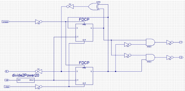
Related Circuits
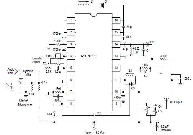
A simple FM transmitter circuit can be designed using the MC2833 integrated circuit, which is intended for cordless telephone and FM communication applications. This circuit includes a microphone amplifier, a voltage-controlled oscillator, and two auxiliary transistors. The final output...
Are you looking for a free schematic and PCB design tool? The gEDA project has produced and continues to work on a complete GPL licensed suite and toolkit for electronic design. The gEDA project offers a comprehensive suite of tools...
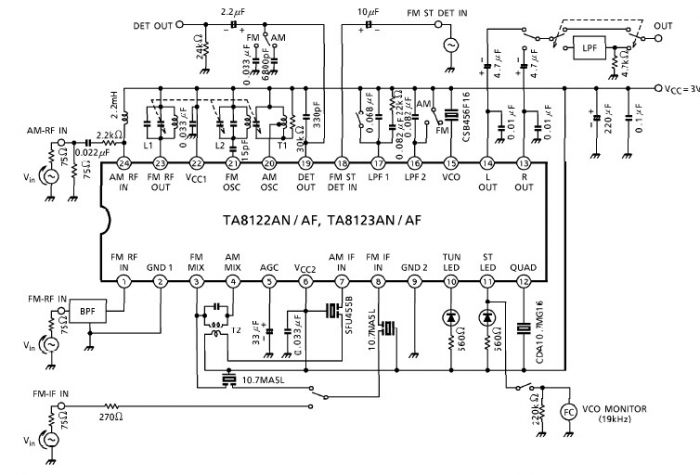
A simple low-power AM/FM radio receiver electronic project can be designed using the TA8122 integrated AM/FM receiver, manufactured by Toshiba Semiconductor. This radio receiver circuit is suitable for portable radio applications or other similar devices. The TA8122 radio receiver...
Create a new project by selecting the New Project option from the Getting Started menu or by selecting File > New Project. This opens a dialog box where the desired project name and location can be entered. Choose a...
A company has developed an intelligent temperature monitoring system using the ATMET 89C51 microcontroller. This system automatically records temperature data for a three-phase power supply, including high temperature and other relevant data, functioning as a black box. The ATMET...
The silicon carbide (SiC) MOSFET offers notable advantages, including a straightforward drive circuit. It possesses unique characteristics that render it a superior switching device in comparison to traditional options. The silicon carbide MOSFET is a type of field-effect transistor that...