
CSC400-Circuit Design
To edit the .ucf file, select it in the Sources window, expand the User Constraints option in the Processes window, and double-click Edit Constraints (Text). A blank text editor will appear. Declare a net titled A and assign it to Pin 124, and declare a net titled B assigned to Pin 38, which correspond to switches sw1 and sw0 on the CoolRunner-II. Additionally, declare a net titled Carry assigned to Pin 68, and a net titled Sum assigned to Pin 69, which correspond to LEDs (LED1 and LED0) on the CoolRunner-II. To generate the programming file, navigate to the Processes window and double-click on Generate Programming File. Address any errors that may arise. Once the program generation is complete, upload the file to the CoolRunner-II by navigating to the project folder to locate the .jed file, double-clicking on it, and selecting Program to load it into the device.
For the Verilog module, define top-level ports for the new module by specifying A and B as input ports, and Carry and Sum as output ports. The reference time unit is set to 1 nanosecond, and precision is set to 1 picosecond.
```verilog
`timescale 1ns / 1ps
//////////////////////////////////////////////////////////////////////////////////
// Company: Smith College
// Engineer: Tiffany Q. Liu
// Create Date: 22:19:35 10/29/2011
// Module Name: TwoBitAdder.v
// Project Name: TwoBitAdder-Verilog
// Target Devices: CoolRunner-II
// Verilog description of a 2-Bit Adder.
// Revision: 11/08/11
// Revision 1.01 - File Created
//////////////////////////////////////////////////////////////////////////////////
module TwoBitAdder(
input A,
input B,
output Carry,
output Sum
);
// Internal wire declaration
wire iA, iB; // Inverse of A and B
wire iCarry, iSum; // Inverse of Carry and Sum
// Gate Instantiations:
// Create inverse A and B signals
not (iA, A);
not (iB, B);
// Create inverse Carry and Sum signals
and (iCarry, iA, iB);
xor (iSum, iA, iB);
// Create Carry and Sum signals
not (Carry, iCarry);
not (Sum, iSum);
endmodule
```
After editing the Verilog module, add a new source to the project by right-clicking on the target device in the Design panel and selecting New Source, or by navigating to Project > New Source. Choose Verilog Test Fixture as the type, assign a meaningful name to the file, and click Next. In the subsequent dialog box, select the modified Verilog module as the source file associated with the test fixture. Click Next and then Finish. To view and edit the Verilog test fixture, change the selected option in the Sources for: drop-down menu from Implementation.Create a new project by selecting the New Project option from the Getting Started menu or by selecting Select File > New Project. This brings up a Dialog box where you can enter the desired project name and location. Choose a meaningful name. You can also place optional comments for your project in the Description text box. Choose Schematic for th e Top-level source type. After clicking Next, select the proper Family, Device, Package, Speed, and Preferred Language for your project. For our CPLD, choose CoolRunner2 CPLDs for Family, XC2C256 for Device, TQ144 for Package, -7 for Speed, and Verilog for Preferred Language.
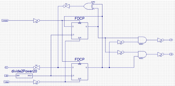
Make sure the Enable Enhanced Design Summary box is checked. Finally, you should see the Project Summary. Make sure all settings are correct before clicking Finish (any modifications to the settings can be made by clicking the Back button. Double click on the new Schematic source that was just created. Under the Symbols tab, choose Logic for the Category. Using the available logic gates from the list, wire up a circuit following the logic equations for c and s from above.
NOTE: Remember that everything is active low on the CoolRunner-II, so be sure to invert the inputs and the outputs to have the CPLD behave in the way that is described by the truth table. Add markers to indicate a, b, carry, and sum. To change the name of markers that are added, double-click on the marker. This brings up the Object Properties dialog box. Highlight Nets and change the Name attribute. The following is an example Schematic: To edit the. ucf file, select it in the Sources window, expand the User Constraints option in the Processes window below and double-click Edit Constraints (Text).
A blank text editor should appear. Declare a net titled A and assign it to Pin 124. Declare a net titled B and assign it to Pin 38. These are the two switches sw1 and sw0 on the CoolRunner-II. Declare another net and title it Carry and assign it to Pin 68, and a final net and title it Sum and assign it to Pin 69. These are two LEDs (LED1 and LED0) on the CoolRunner-II. Generate programming file: Go to the Processes window and double-click on Generate Programming File. Debug any errors that may occur. Once the program generation processes comes to a completion, you can upload the file to your CoolRunner-II.
Next, click on ". " and navigate to your project folder to find the. jed file. Double-click on the. jed file and click on Program to load it into your CoolRunner-II. Create a new project by selecting the New Project option from the Getting Started menu or by selecting Select File > New Project. This brings up a Dialog box where you can enter the desired project name and location. Choose a meaningful name. You can also place optional comments for your project in the Description text box. Choose HDL for the Top-level source type. After clicking Next, select the proper Family, Device, Package, Speed, and Preferred Language for your project.
For our CPLD, choose CoolRunner2 CPLDs for Family, XC2C256 for Device, TQ144 for Package, -7 for Speed, and Verilog for Preferred Language. Make sure the Enable Enhanced Design Summary box is checked. Finally, you should see the Project Summary. Make sure all settings are correct before clicking Finish (any modifications to the settings can be made by clicking the Back button.
You should now have the option of defining top-level ports for the new Verilog module. Type in A and B for input ports and Carry and Sum for output ports. Click Next. //Reference time unit set to 1 nanosecond and precision is 1 picosecond `timescale 1ns / 1ps ////////////////////////////////////////////////////////////////////////////////// // Company: Smith College // Engineer: Tiffany Q. Liu // // Create Date: 22:19:35 10/29/2011 // Module Name: TwoBitAdder. v // Project Name: TwoBitAdder-Verilog // Target Devices: CoolRunner-II // Verilog description of a 2-Bit Adder.
// // // Revision: 11/08/11 // Revision 1. 01 - File Created // ////////////////////////////////////////////////////////////////////////////////// module TwoBitAdder( input A, input B, output Carry, output Sum ); //Internal wire declaration wire iA, iB; //Inverse of A and B wire iCarry, iSum; //Inverse of Carry and Sum //Gate Instantiations: //Create inverse A and B signals: not (iA, A); not (iB, B); //Create inverse Carry and Sum signals: and (iCarry, iA, iB); xor (iSum, iA, iB); //Create Carry and Sum signals: not (Carry, iCarry); not (Sum, iSum); endmodule To edit the. ucf file, select it in the Sources window, expand the User Constraints option in the Processes window below and double-click Edit Constraints (Text).
A blank text editor should appear. Declare a net titled A and assign it to Pin 124. Declare a net titled B and assign it to Pin 38. These are the two switches sw1 and sw0 on the CoolRunner-II. Declare another net and title it Carry and assign it to Pin 68, and a final net and title it Sum and assign it to Pin 69. These are two LEDs (LED1 and LED0) on the CoolRunner-II. Generate programming file: Go to the Processes window and double-click on Generate Programming File. Debug any errors that may occur. Once the program generation processes comes to a completion, you can upload the file to your CoolRunner-II.
Next, click on ". " and navigate to your project folder to find the. jed file. Double-click on the. jed file and click on Program to load it into your CoolRunner-II. //Reference time unit set to 1 nanosecond and precision is 1 picosecond `timescale 1ns / 1ps ////////////////////////////////////////////////////////////////////////////////// // Company: Smith College // Engineer: Tiffany Q. Liu // // Create Date: 22:19:35 10/29/2011 // Module Name: TwoBitAdder. v // Project Name: TwoBitAdder-Verilog // Target Devices: CoolRunner-II // Verilog description of a 2-Bit Adder.
// // // Revision: 11/08/11 // Revision 1. 01 - File Created // ////////////////////////////////////////////////////////////////////////////////// module TwoBitAdder( input A, input B, output Carry, output Sum ); //Gate Instantiations: //Create Carry and Sum signals: and (Carry, A, B); xor (Sum, A, B); endmodule After editing the Verilog module, add a new source to the project. To do this, either right-click on the target device in the Design panel and choose New Source or go to Project > New Source.
Choose Verilog Test Fixture for the type and give the file a meaningful name, and click Next. In the following dialog box, select the Verilog module that you just modified as the source file you want to associate with the given test fixture file. This selects the source file you actually run the simulation on. Click Next and Finish. To view and edit the Verilog test fixture, first change the selected option in the Sources for: drop-down menu from Implementation key features
🔗 External reference
Related Circuits
This document presents a very low-power monolithic 1.9GHz silicon Low Noise Amplifier (LNA) that operates with a total current consumption of 1.75mA, which includes the bias circuit. The described Low Noise Amplifier (LNA) operates at a frequency of 1.9GHz, making...
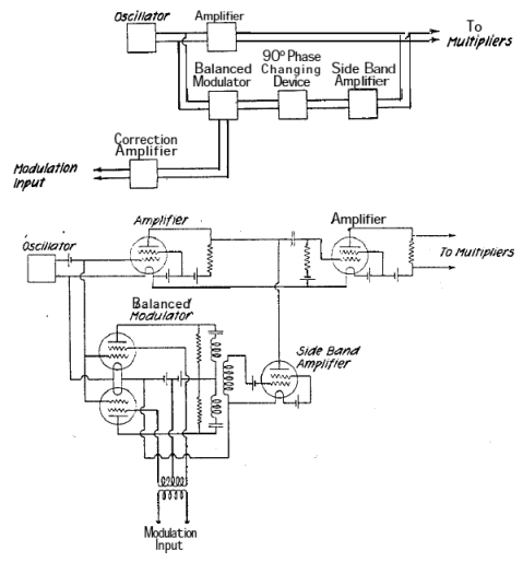
A system is being developed to transmit in the FM band. The oscillators have already been constructed to facilitate transmission across multiple frequencies. The design of an FM transmission system involves several key components, including oscillators, modulators, amplifiers, and antennas....
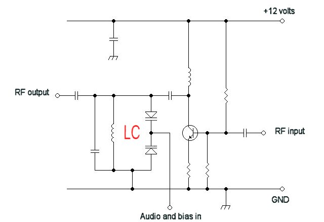
For a fixed frequency transmitter, a common method is to use a resonant quartz crystal in a crystal oscillator to establish the frequency. In transmitters where the frequency must be variable, several options are available. It is often the...
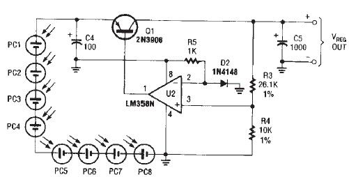
The circuit diagram illustrates a portable solar charger that utilizes an LM358N operational amplifier and a single transistor. This regulator delivers a constant output of 2.4 volts DC, suitable for powering small devices requiring energy from two AA battery...
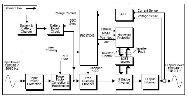
The UPS (Uninterruptible Power Supply) Reference Design offers a pre-designed uninterruptible power supply solution utilizing the flexibility of the PIC17C43 microcontroller. This microcontroller is noted for its low-cost and high-performance capabilities, which are not typically found in other microcontrollers....
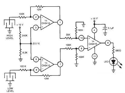
This liquid level sensor electronic circuit diagram utilizes a common CA3410 operational amplifier integrated circuit (IC). The sensor employs two plate sensors (or probes), one designated for detecting high liquid levels and the other for low liquid levels. If...
Warning: include(partials/cookie-banner.php): Failed to open stream: Permission denied in /var/www/html/nextgr/view-circuit.php on line 713
Warning: include(): Failed opening 'partials/cookie-banner.php' for inclusion (include_path='.:/usr/share/php') in /var/www/html/nextgr/view-circuit.php on line 713