
relay tutorial

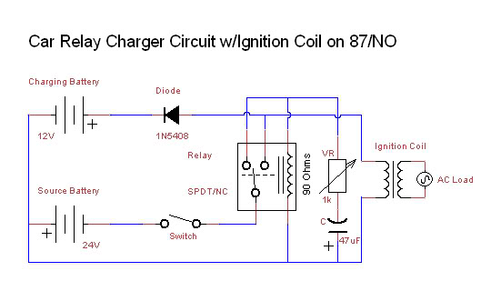
The relay operates as a crucial component in controlling higher power circuits with low-power control signals. It allows for the isolation of sensitive components from high-voltage or high-current loads, which is essential for protecting microcontrollers such as the Arduino. The diode placed across the relay coil, often referred to as a flyback or freewheeling diode, serves to redirect the inductive kickback generated when the relay coil is de-energized. This diode is typically a standard rectifier diode, such as the 1N4001, capable of withstanding the reverse voltage generated during this process.
In practical applications, the relay's mechanical components, including the armature and contacts, are designed to handle specific electrical loads. The choice of relay should be matched to the application's requirements, considering both the voltage and current ratings. For instance, in scenarios where the load exceeds the relay's 1 amp rating, a larger relay with a suitable rating should be selected.
In summary, relays provide a reliable means of controlling high-power circuits through low-power signals, enhancing the functionality and safety of electronic systems. Their various configurations allow for versatile applications in automation, switching, and control systems.A relay is an electro-mechanical switch that opens and closes under the control of another electric circuit. When current flows through the coil of the relay, a magetic field is created that causes an armature to move, either making or breaking an electrical connection.
When current is removed from the relay coil, the armature returns to its rest position. It is important to place a diode across the coil of the relay because a spike of voltage is generated when the current is removed from the coil due to the collapse of the magnetic field. This voltage spike can damage the sensitive electronic components controlling the circuit. The relay we are using in this example has a coil voltage of 5VDC, meaning the relay switch will be activated when 5VDC is supplied across the relay coil.
The output pin of an Arduino does supply 5VDC, but the current that the relay requires to activate its switch is greater than the Arduino can safely supply. In this case, a 2N3904 transistor is used to supply a higher current 5VDC source to the relay coil (see multiple LEDs tutorial for more information on this circuit).
The primary reason to use a relay is to switch a circuit of higher current than the Arduino is able to directly handle. A relay switch is much slower than a transistor, but has advantages in certain situations. When using a transistor to switch a higher current and/or voltage circuit, both the controller and switched currents need to share a common ground.
There are times when this is not an option (such as switching an AC current circuit with a DC control circuit) and using a relay can be an option because it provides a mechanical separation between the circuits. Like standard manually operated manual switches, relays come with many different arrangements of switch poles and contacts, such as SPST (single pole, single throw - the relay type used in this example), SPDT (single pole, double throw), DPST (double pole, single throw), DPDT (double pole, double throw), among many others.
The relays will have a coil voltage rating, which determines the voltage and current that is necessary to supply to the coil to activate the relay, as well as a rating of maximum current and/or voltage that can be passed through the switch (the relay we are using in this example is small and can only handle 1 amp of current through its switch - larger relays are common and can safely switch much higher currents. 🔗 External reference
Related Circuits
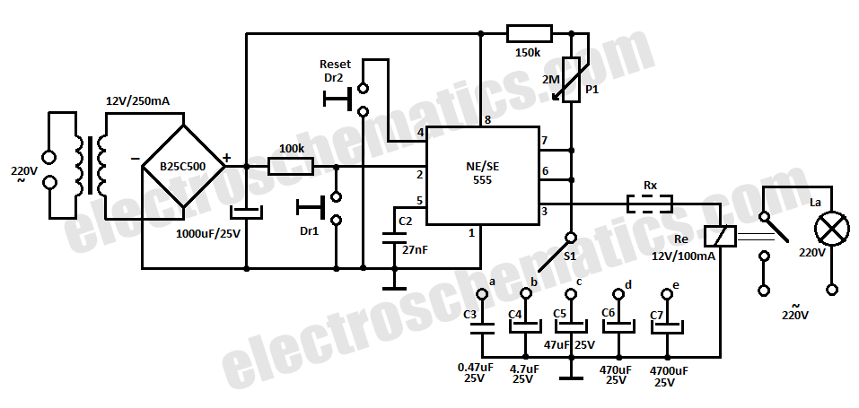
This component is equivalent to a single-pole electromechanical latching relay with an electrically isolated solenoid. Once activated, the circuit remains in a conductive state even if the line voltage is interrupted for extended periods. A positive reset action necessitates...
A new member has joined the forum and is seeking assistance with electronics, particularly from a technical engineering perspective, although they have some experience with circuits and schematics. The individual is likely looking to enhance their understanding of electronic components,...
Dual Channel Relay Board is a simple and convenient way to interface 2 relays for switching application in your project. Input - 12 VDC @ 84 mA. Output - two SPDT relay. Relay specification - 5 A @ 230...
4 Channel Infrared (IR) Remote is a simple kit using the famous HT12A and HT12D encoder/decoder chips from Holtek. The 4 Channel Infrared (IR) Remote system utilizes the HT12A and HT12D integrated circuits to facilitate wireless communication between a transmitter...
One advantage of a solid-state relay (SSR) over a conventional electromagnetic relay (EMR) is its wear-free operation. The S201S01 from Sharp is a notable example. Solid-state relays (SSRs) are electronic switching devices that use semiconductor components to perform the switching...
This circuit allows a 12v relay to operate on a 6v or 9v supply. Most 12v relays need about 12v to "pull-in" but will "hold" on about 6v. The 220u charges via the 2k2 and bottom diode. When an...