
Remote Control Tester
The following diagram illustrates the circuit schematic for a 12V stereo tone control, which is also available as a kit at local electronic parts stores. The circuit is based on a standard tone control design, utilizing two FCS9014 transistors in each channel, totaling four transistors for the 12V configuration. Additionally, a low resistance connection tester can be employed as a cable or wire tester, suitable for soldered joints and other types of connections with resistance values between 0.25 and 4 ohms. This simple circuit uses a 741 op-amp in differential mode as a continuity tester, measuring the voltage difference between the non-inverting and inverting inputs.
Furthermore, the following diagram represents the schematic for an Active Tone Control circuit, commonly referred to as "ACTOR." The Active Tone Control circuit enhances the loudness of audio signals (bass and treble) using the Baxandall system. This circuit does not require a dedicated power supply.
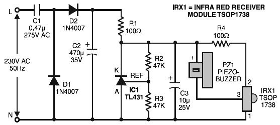
Lastly, there is a description of a wireless car alarm system constructed using two circuit modules: a transmitter module and a receiver module. This system operates on FM radio waves and is compatible with vehicles that have a 6-12V DC power supply. A voltage stabilizer can be employed if the car's power supply exceeds this range.Remote control tester circuit diagram. The tester is designed around infrared receiver module TSOP1738. Operation of the remote control is identified by a tone from the buzzer. The circuit is sensitive and has a range of about 5 metres. The integrated IR receiver detects, amplifies and demodulates IR signals from the remote control unit. The piezo buzzer connected at its output sounds to tell us the existence of transmission from the remote control unit. Here is the remote control tester circuit. This circuit is really a simple and easy tester for verifying the basic operations of an infrared remote control unit.
It is low-cost and very easy to construct. The tester is designed around infrared receiver module TSOP1738. Operation of the remote control is identified by a tone from. The circuit, consisting of an infrared transmitter-receiver pair, utilizes IR beam transmission to switch the toy car on` or off`, yeah. it will be only switching on and switching off, you may modify this circuit to make the toy car to turn left or right.
To operate the toy car, you have to hold the. The following diagram is the circuit diagram of 12V stereo tone control which also available in kit, you may find the kit at electronic part store around your place. The circuit build based on ordinary tone control circuit, using 2 transistors FCS9014 in each channel, so there are will be 4 transistors in this 12v.
Here the low resistance connection tester which can be used as cable or wire tester, soldered joints and other types of connection with resistance value between 0. 25 and 4 ohm. Notes This simple circuit uses a 741 op-amp in differential mode as a continuity tester. The voltage difference between the non-inverting and inverting inputs is. The following diagram is the schematic diagram of Active Tone Control circuit, or we often call thic circuit as "ACTOR" Active Tone Control or ACTOR is a electronic audio circuit that serves to increase the Loudness (Bass and Treble audio signal) is active because it uses the Baxandall system.
This circuit does not use a. This circuit is a wireless car alarm system that is built using two circuit modules, namely modules of transmitter and receiver modules. This circuit works on FM radio waves. Car alarms can be used on vehicles that have a 6-12VDC power supply. You can use the voltage stabilizer if your car power supply is too. 🔗 External reference
Related Circuits
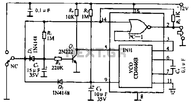
The figure illustrates a circuit involving dark tomb electric locks, specifically the fti: al: 4046B and XOR gate as the primary control mechanism. It emits pulses and utilizes silicon for successive pulse generation. The circuit operates with a normal...
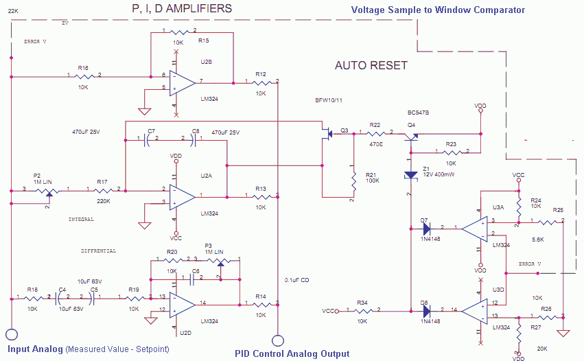
The Measured Value and the Setpoint are two inputs to a control system. The Measured Value is the amplified input from a transducer or sensor for a specific parameter that requires regulation, such as pressure or temperature. The Setpoint...
The temperature of a quartz crystal oscillator must be maintained at a constant level to ensure stable frequency operation. This oven temperature controller is appropriate for this purpose. The operation of quartz crystal oscillators relies heavily on temperature stability, as...
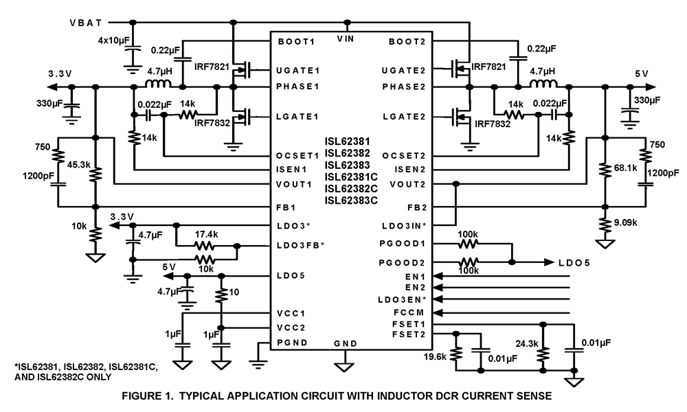
The ISL62381, ISL62382, ISL62383, ISL62381C, ISL62382C, and ISL62383C family of controllers generate supply voltages for battery-powered systems. These controllers include two pulse-width modulation (PWM) controllers, adjustable from 0.6V to 5.5V, and two linear regulators, LDO5 and LDO3, that generate...
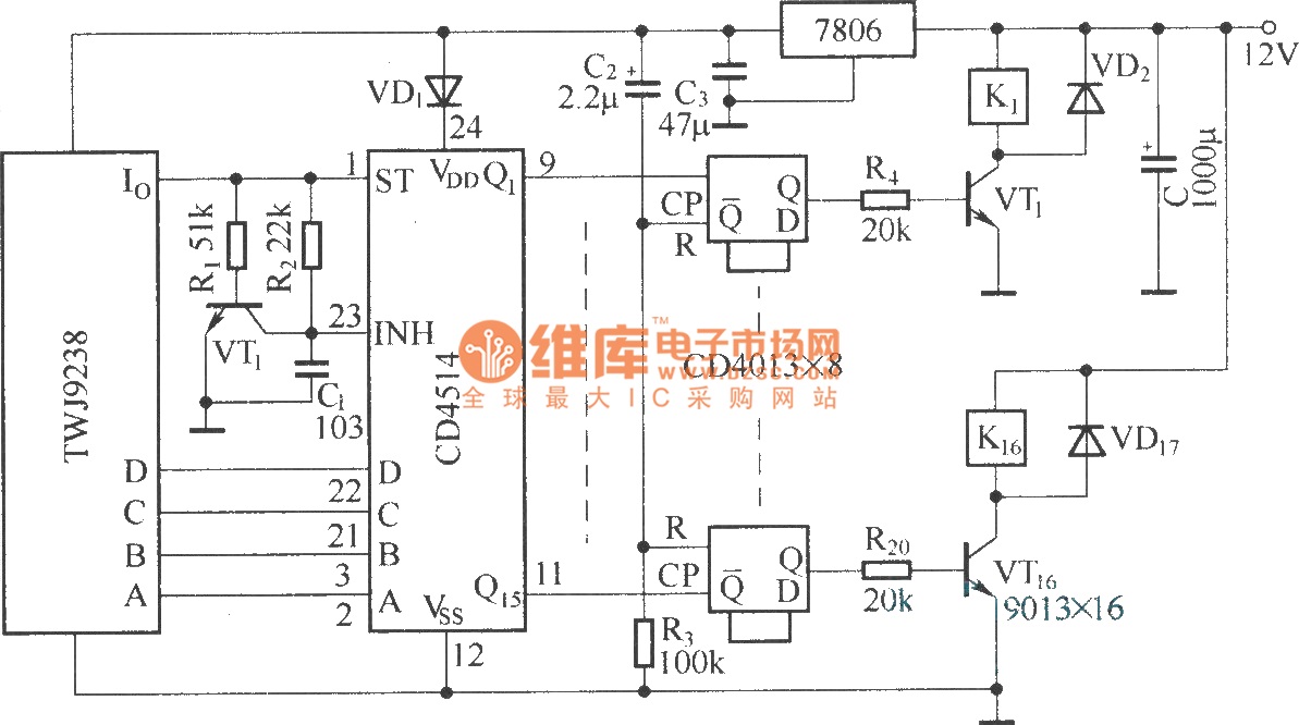
The Sixteenth Street control circuit consists of a secondary decoding output control circuit. Each output terminal of the sixteen decoding is connected to a bistable circuit made up of dual D flip-flops (CD4013). A DC relay is connected to...
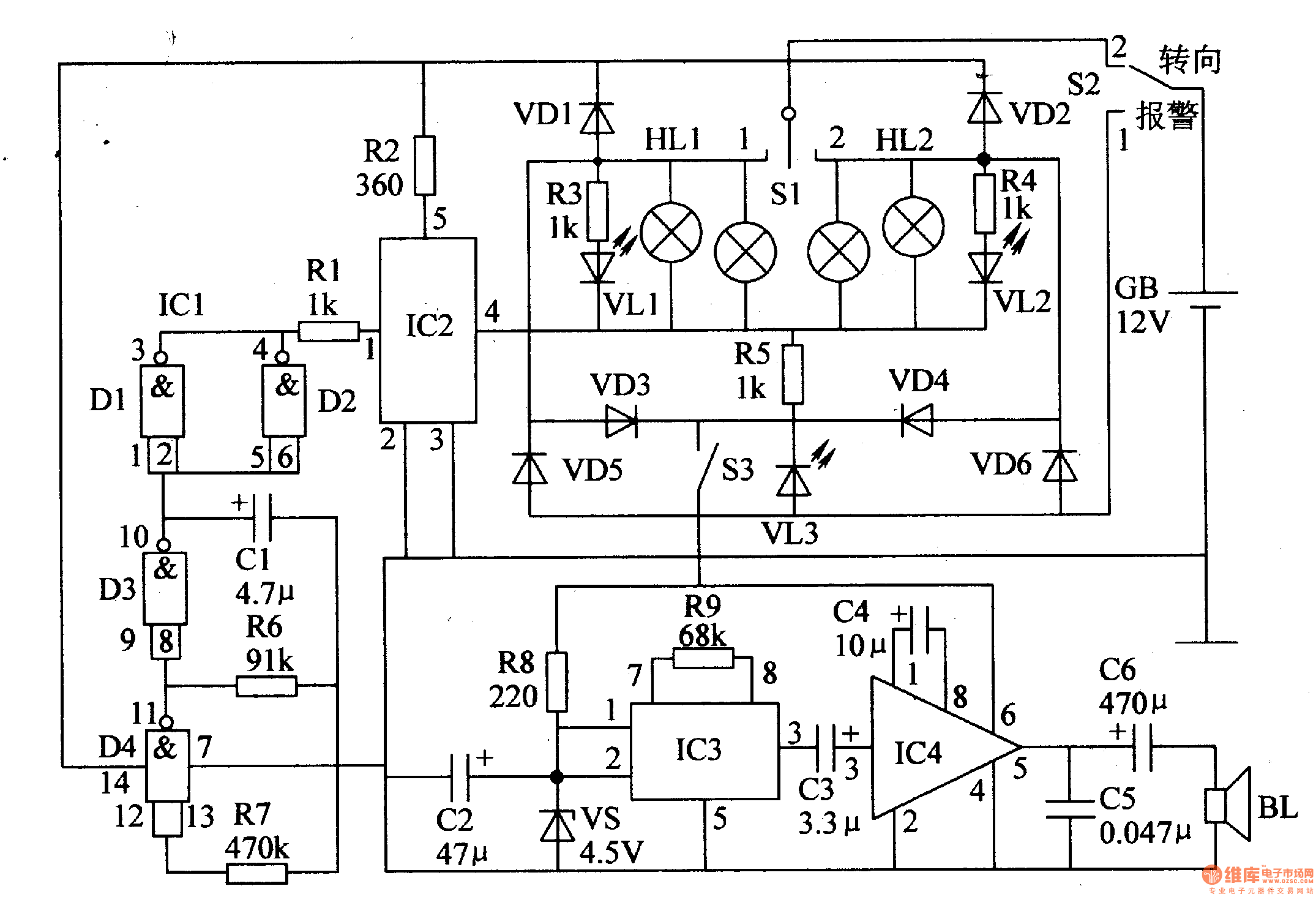
The circuit comprises a low-frequency oscillator, an electronic switch circuit, a control circuit, a photoelectric display circuit, and a music alarm circuit. The low-frequency oscillator is constructed using an integrated circuit (IC) with internal NAND gates and external resistor-capacitor...