
analog pid control using opamps
The control system outlined operates on a feedback mechanism that continuously monitors the process variable (the Measured Value) against the desired target (the Setpoint). This feedback loop is essential for maintaining stability and accuracy in various applications. The PID controller's three components—proportional, integral, and derivative—each play a distinct role:
1. **Proportional Control**: This component produces an output that is proportional to the current error value. It provides immediate correction based on the magnitude of the error, thereby driving the system towards the Setpoint. However, solely relying on proportional control can result in a steady-state error.
2. **Integral Control**: This component accumulates the error over time, addressing any residual steady-state error that the proportional control cannot eliminate. The integrator adjusts the output based on the sum of past errors, ensuring that the process variable aligns closely with the Setpoint over time.
3. **Differential Control**: This component predicts future errors based on the rate of change of the error. By anticipating the direction and speed of the error change, the differentiator can apply corrective actions preemptively, reducing overshoot and improving system response time.
The combined output from these three components is processed to generate a control signal that effectively drives the actuator. The actuator's response must be appropriately matched to the system dynamics; thus, careful consideration is required during the design phase to ensure that the control system functions optimally under varying conditions.
In applications where rapid response is critical, such as in temperature control of fast-heating processes, the PID parameters must be tuned meticulously to achieve the desired performance without introducing instability. Tuning may involve adjusting gain settings for each PID component, and methods such as Ziegler-Nichols or software-based optimization techniques can be employed to achieve optimal results.
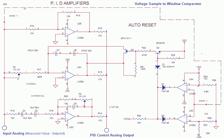
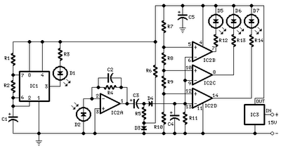
Overall, the described control system exemplifies the integration of analog and digital techniques to achieve precise control over physical parameters, ensuring efficiency and reliability in industrial and commercial applications.The Measured Value and The Setpoint are two inputs to a Control System. The Measured Value is the Amplified input of a Transducer or Sensor for some Parameter that needs to be controlled. It could be Pressure or Temperature. etc. The Setpoint is the User Defined Input using a Potentiometer, Thumbwheel, EPROM or Flash Value. This is the value at whi ch the process has to be maintained for that parameter. The difference of these two is the Error, this is the input for this PID Analog Computation Stage. The three Opamps are configured as Proportional, Integrator and Differentiator Amps. The Addition or Summation of these Values is the PID Control Output. (These days it is Math in the Firmware on a MCU, DSP or Software Application in SCADA) This Analog PID Control Output can now be translated to a 4-20 mA Control Signal, that means 0-100% of power to the Actuator, which could be a Heater, Pump, Fan, Motor using AC/DC Drives. It could be a Steam Valve, Pneumatic or Hydraulic Motorized/Solenoids. The Actuator Size/Array must be right for the Process, a tiny fan cannot cool a Large Furnace, a small solenoid valve cannot fill a Big Tank.
An effective Proportional or PID control depends on choosing or designing the Sensor, Actuator and System Environment prudently. The Auto Reset is needed to ensure the Integrator does not dampen the Process so much that it fails to even raise to the Process value fast enough (Diffrentiator).
So in the Proportional Band the Integrator is Active. If the Setpoint is 1000 deg C, the proportional band is 10%. The Raise of temperature till 950 deg is Undampended. After that Integrator is called in by the Window Comparator made of two opamps, the integrator prevents OverShoot, Undershoot, Ringing and Oscillations. The PID control output can also be a Time Proportional Output like PWM. With a large cycle time of 20 or More seconds. Like 2 Seconds on and 18 Seconds off for 10% Control. Fast Cycle times may be needed for small systems with less inertia. 🔗 External reference
Related Circuits
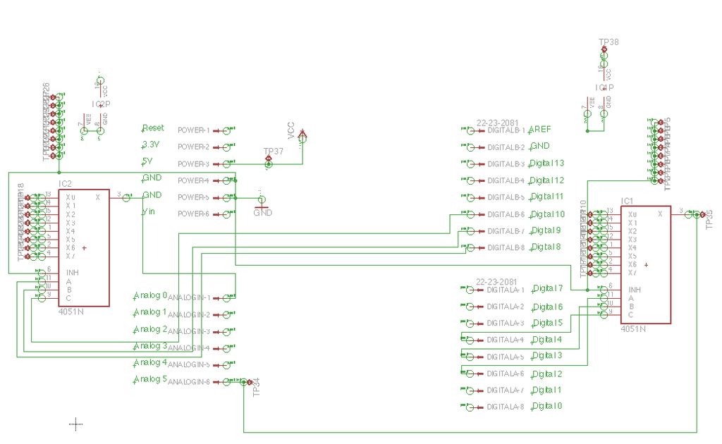
Inspired by a previous project, a unique design was developed that incorporates an umbrella capable of playing musical notes when pressed. For additional information regarding the 4051 chip, which functions as a multiplexer or demultiplexer, refer to resources available...
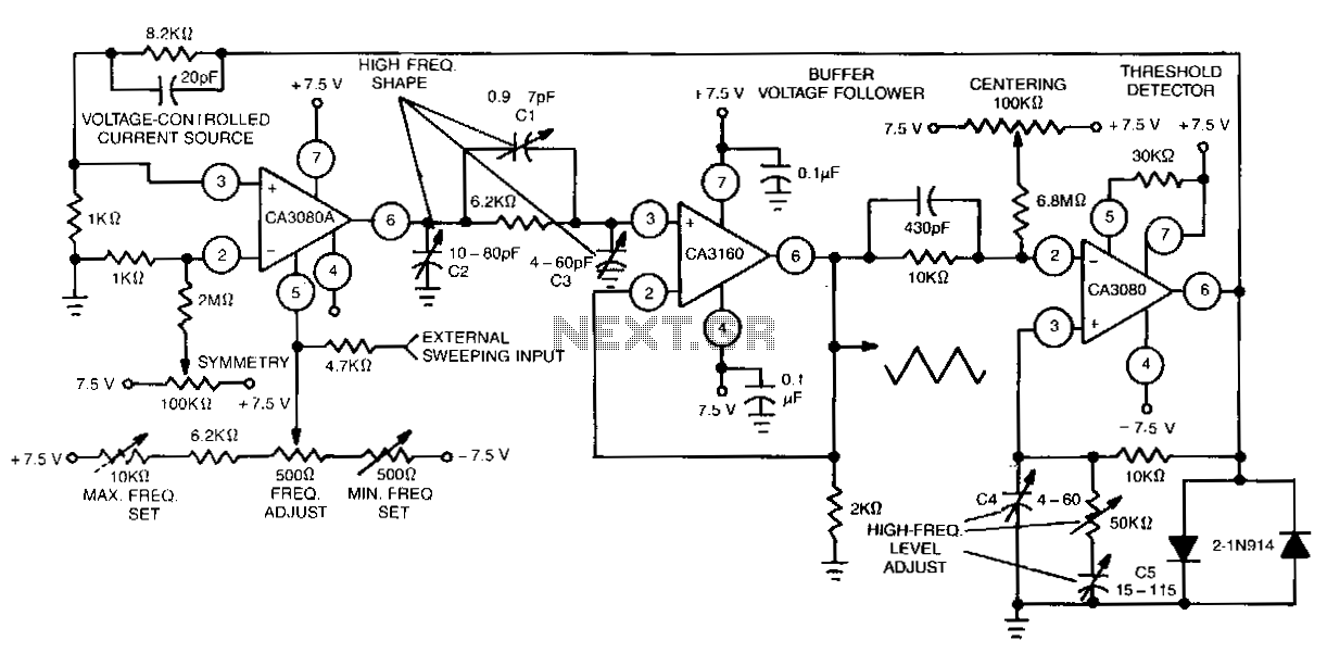
This function generator features an adjustment range exceeding 1,000,000 to 1 and utilizes a CA3160 BiMOS operational amplifier as a voltage follower. It incorporates a CA3080 operational transconductance amplifier (OTA) as a high-speed comparator, alongside another CA3080 configured as...
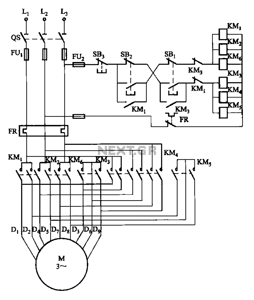
The circuit illustrated in Figure 3-107 features a low-speed operation button (SBi) and a high-speed operation button (SB2). The circuit design depicted in Figure 3-107 integrates two operational modes controlled by distinct buttons: SBi for low-speed operation and SB2 for...
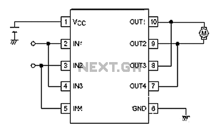
A simple motor control project for forward and backward drive can be implemented using the LB1948M motor driver IC, which features two channels for motor control. The LB1948M is an ideal choice for 12V motor drive systems and can...
All distances mentioned can vary depending on the infrared transmitting and receiving LEDs used and are significantly affected by the color of the reflecting surface. Black surfaces greatly reduce the device's sensitivity. This circuit can also be applied in...

This project focuses on the design and development of a theft control system for automobiles, aimed at preventing and controlling vehicle theft. The system utilizes an embedded design based on GSM and GPS technology. It is installed within the...