
Remote Control Toy Car Schematic
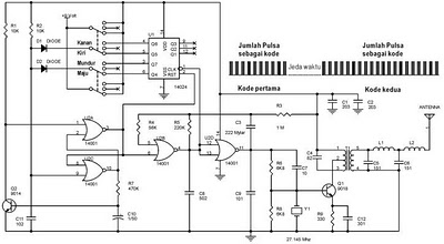
The remote control toy car circuit typically consists of several key components that enable wireless control and operation. The main elements include a transmitter, a receiver, a motor driver, and the toy car's DC motors.
The transmitter is generally equipped with a control interface, such as a joystick or buttons, which sends radio frequency (RF) signals to the receiver. The transmitter circuit may include a microcontroller that processes user inputs and modulates the RF signal for transmission.
The receiver, located within the toy car, is designed to decode the incoming RF signals. It usually incorporates a demodulator and a microcontroller that interprets the commands and controls the motor driver accordingly.
The motor driver is a crucial component that interfaces between the receiver and the DC motors. It amplifies the control signals from the receiver and provides the necessary current to drive the motors. Commonly, an H-bridge configuration is used, allowing for bidirectional control of the motors, which enables forward, reverse, and turning maneuvers.
The DC motors are responsible for propelling the toy car. They are typically equipped with gear systems to enhance torque and speed. Power for the entire circuit is usually supplied by a battery pack, which must be adequately rated to ensure sufficient operational time and performance.
Overall, the remote control toy car circuit is designed to be user-friendly, providing a seamless interface for operation while maintaining the integrity of the original toy's performance. The careful selection and integration of components are essential to ensure reliability and responsiveness in the toy car's movements.The following circuit shows about Remote Control Toy Car Schematic Circuit Diagram. Features: does not impose on the performance of the original .. 🔗 External reference
Related Circuits
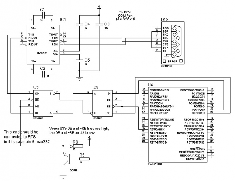
The circuit in Figure 1 is an RS-232/485 converter that uses the transmitted signal itself to control the flow. The circuit uses MAX232 and MAX483 interface circuits, IC1 and IC2 from Maxim Integrated Products to convert between the ICs'...
Best Microcontroller Projects. Do you want to learn how to use a microcontroller in your electronic projects, or do you need inspiration for your next project? If so, you have found the right place! Here is a tutorial on...
The adjustment control for the contrast of an LC-Display typically utilizes a 10-kilohm potentiometer. This arrangement functions adequately, provided that the power supply voltage remains constant. However, in situations where the power supply is variable, such as with a...
The limitation of car supply voltage (12V) forces to convert the voltages to higher in order to power audio amplifiers. This supply is intended for two channels with 50W max each (of course it depends on the amplifier used)....
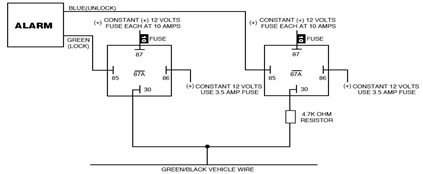
The following circuit illustrates the Ford Probe Single Wire Door Alarm System. This Single Door Locking Wire manages both LOCK and UNLOCK functions, indicating that the pulse wires must be connected to the same vehicle wire. The system primarily...
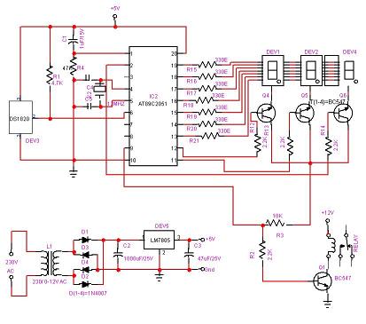
The ability to turn electrical devices ON or OFF using a remote control is a well-established concept, with numerous devices effectively performing this function. To implement a remote control system for switching electrical devices, a typical schematic would include several...