
Contrast Control for LCDs

The circuit design incorporates the LM334 integrated circuit, which is essential for establishing a constant current source. The LM334 is configured with a resistor (R1) to set the desired output current. The choice of a 2.2-kilohm potentiometer allows for flexibility in adjusting the output current to meet specific display requirements. The circuit ensures that the current flowing through the contrast pin of the LC display remains stable, thereby maintaining optimal display performance without the need for constant manual adjustments.
In practical applications, the circuit is connected such that the output of the LM334 feeds into the contrast control pin of the LC display, while the other end connects to ground. This configuration allows the LM334 to maintain a consistent current regardless of fluctuations in the power supply voltage. The power savings achieved through this method are significant, particularly in battery-operated devices where energy conservation is crucial.
The temperature dependency of the LM334's output current is a critical consideration. While the current drawn by the display may also vary with temperature, the circuit is designed to tolerate variations of up to 10 °C without compromising performance. This robustness makes the circuit suitable for a variety of operating conditions.
For applications involving OLED or PLED displays, careful testing is recommended to verify that the circuit can effectively adjust brightness without adversely affecting display characteristics. The formula provided for calculating R1 allows for precise adjustments based on temperature and desired current levels, ensuring that the circuit can be tailored to specific operational requirements. Overall, this circuit represents a practical solution for maintaining consistent contrast in LC displays while enhancing energy efficiency in battery-powered applications.The adjustment control for the contrast of an LC-Display is typically a 10-k potentiometer. This works fine, provided that the power supply voltage is constant. If this is not the case (for example, with a battery power supply) then the potentiometer has to be repeatedly adjusted. Very awkward, in other words. The circuit described here offers a s olution for this problem. The aforementioned potentiometer is intended to maintain a constant current from the contrast connection (usually pin 3 or Vo) to ground. A popular green display with 2G—16 characters supplies` about 200 µA. At a power supply voltage of 5 V there is also an additional current of 500 µA in the potentiometer itself.
Not very energy efficient either. Now there is an IC, the LM334, which, with the aid of one resistor, can be made into a constant current source. The circuit presented here ensures that there is a current of 200 µA to ground, independent of the power supply voltage.
By substituting a 2. 2-k potentiometer for R1, the current can be adjusted as desired. Note that the current supplied by the LM334 depends on the temperature. This is also true for the current from the display, but it is not strictly necessary to have a linear relationship between these two. Temperature variations of up to 10 ° will not be a problem however. This circuit results in a power saving of over 25% with an LCD that itself draws a current of 1. 2 mA. In a battery powered application this is definitely worth the effort! In addition, the contrast does not need to be adjusted as the battery voltage reduces. When used with LCDs with new technologies such as OLED and PLED it is advisable to carefully test the circuit first to determine if it can be used to adjust the brightness.
The value of R1 can be calculated as follows: R1 = 227G—10-6 x T / I. Where T is the temperature in Kelvin and I is the current in ampG¨res. In our case this results in: The current supplied by the LM334 depends on the temperature. This is also true for the current from the display, but it is not strictly necessary to have a linear relationship between these two. Temperature variations of up to 10 ° will not be a problem however. This circuit results in a power saving of over 25% with an LCD that itself draws a current of 1. 2 mA. In a battery powered application this is definitely worth the effort! In addition, the contrast does not need to be adjusted as the battery voltage reduces. When used with LCDs with new technologies such as OLED and PLED it is advisable to carefully test the circuit first to determine if it can be used to adjust the brightness.
🔗 External reference
Related Circuits
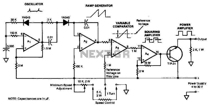
The quad operational amplifier circuit provides a pulse width modulation control ranging from 0 to 100 percent. The controller utilizes an LM3900 and operates with a single supply voltage between 4 to 30 V. A 1 kHz oscillator amplifier,...
The controller uses one or more ordinary silicon diodes as a sensor, and uses a cheap opamp as the amplifier. I designed this circuit to use 12V computer fans, as these are now very easy to get cheaply. These...
For controlling a small DC motor, such as the one found in a tape recorder, Q1 and Q2 are in saturation when both points A and B are HIGH. Component: .. To control a small DC motor effectively, a circuit...
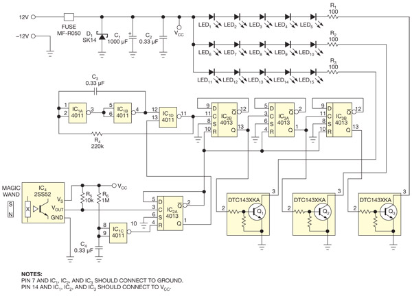
This circuit enables the activation of holiday bulbs with a wave of a magic wand. The strings of lights flash in a sequential manner. The core concept relies on a magnet. The circuit operates by utilizing a magnet as the...
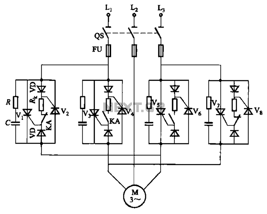
The circuit depicted in Figure 3-69 is designed for applications requiring frequent timing control for motor reversing operations. In this configuration, thyristors V1, V2, V7, and V5 are utilized for positive control of rotation, while thyristors V3, V4, and...
The following circuit illustrates a stepper motor controller. This circuit is based on the PIC16F84A integrated circuit. Features: a transistor is utilized to drive the motor. The stepper motor controller circuit employs the PIC16F84A microcontroller, which serves as the central...