
Removing pop from a CMOS switch
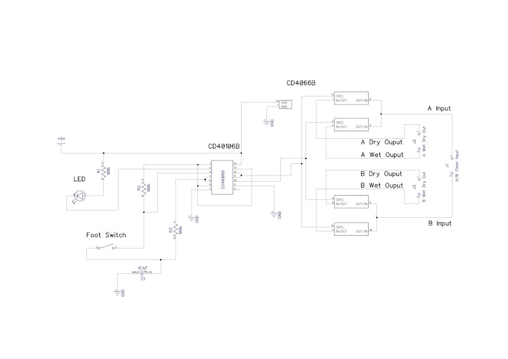
The circuit design incorporates a CD40106 Schmitt Trigger, which is essential for providing clean signal transitions and noise immunity. The Schmitt Trigger can convert slow or noisy input signals into sharp, clean output signals, making it suitable for audio applications where signal integrity is crucial. The output of the CD40106 is connected to the control input of the CD4066, a quad bilateral switch. This switch allows for the routing of audio signals based on the output state of the Schmitt Trigger.
In operation, when the Schmitt Trigger detects a high logic level, it activates the corresponding switch within the CD4066, allowing audio signals to pass through to the desired output. Conversely, when the output from the Schmitt Trigger is low, the switch is turned off, effectively blocking the audio signal. This arrangement enables the selection between different audio sources or outputs, providing flexibility in audio routing.
For optimal performance, it is important to ensure that the power supply levels for both the CD40106 and CD4066 are compatible and that the input signals remain within the specified voltage levels to prevent damage and ensure reliable operation. Additionally, proper decoupling capacitors should be placed near the power pins of both ICs to minimize noise and voltage fluctuations that could affect circuit performance.
In summary, this audio switching circuit leverages the properties of the CD40106 Schmitt Trigger and the CD4066 CMOS switch to create a reliable and efficient method for routing audio signals, suitable for various applications in audio electronics.Hi again, I have a simple audio switching circuit that is giving me a problem. I am using a CD40106 Schmitt Trigger in conjunction with a CD4066 CMOS switch to route.. 🔗 External reference
Related Circuits
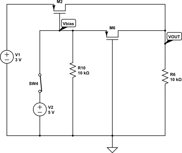
The output voltage (VOUT) is intended to be 3V when the switch is open and 5V when the switch is closed. The simulation correctly reflects the desired outcome when the switch is open; however, it does not perform as...
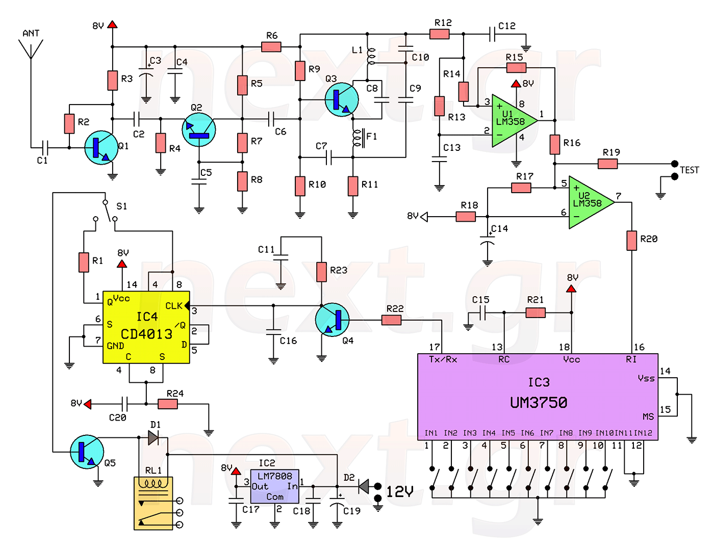
This circuit includes a 2048 radio remote control transmitter and a corresponding wireless receiver that features high reception sensitivity and low power consumption. The combination of these two components provides a highly reliable remote control system, suitable for various...
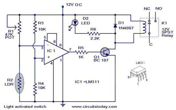
A simple light-activated switch circuit with a diagram and schematic using IC LM311 wired as a voltage comparator and an LDR that acts as a light sensor. The described circuit utilizes the LM311 integrated circuit, which functions as a voltage...
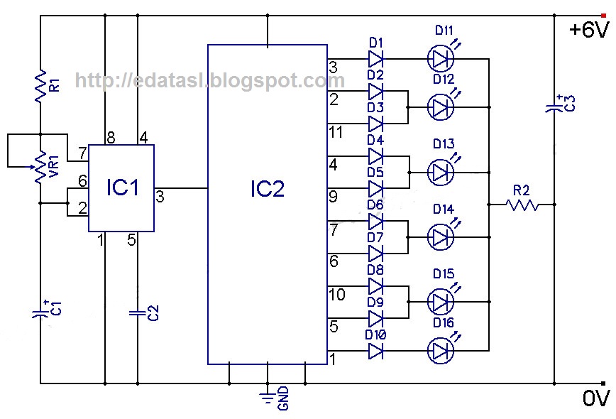
At the onset of the second clock cycle, the output labeled "0" transitions to a LOW state while the output labeled "1" transitions to a HIGH state. This sequence persists across ten outputs, eventually cycling back to output "0"...
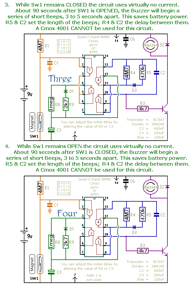
This document presents a collection of compact, self-contained alarm circuits. These circuits are designed to operate with a very low standby current, making them ideal for battery-powered applications. They can be triggered by both normally-open and normally-closed switches, while...
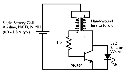
This circuit is commonly referred to as a Joule Thief, and it has been frequently encountered in various electronics videos on YouTube. The Joule Thief is a simple, low-cost circuit designed to extract energy from a single-cell battery, particularly when...