
4017 CMOS Decade Counter
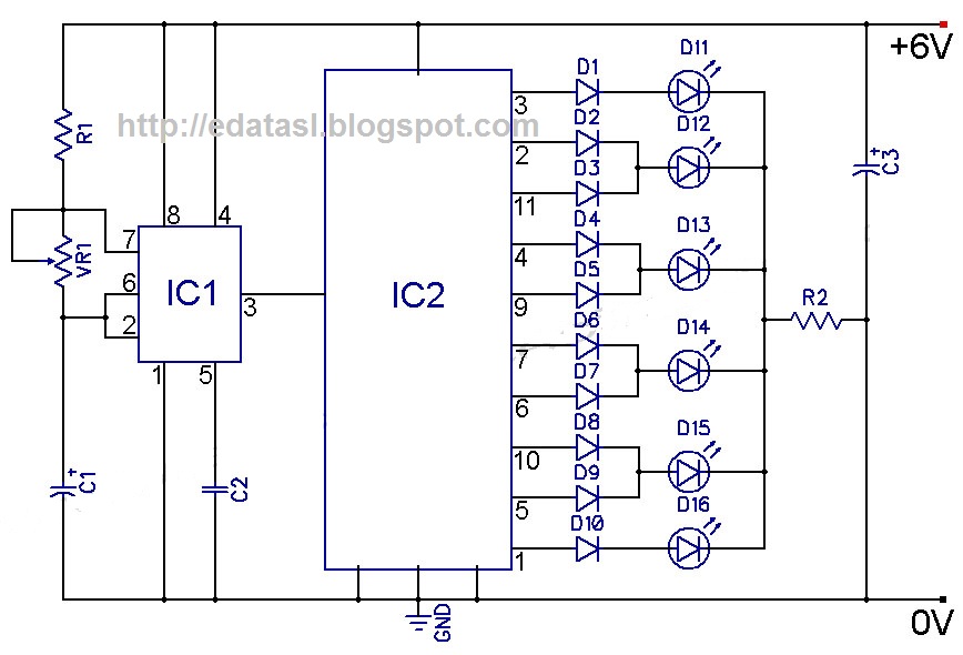
The described circuit appears to function as a sequential output generator that relies on clock cycles to control the state of multiple outputs. In this configuration, the clock signal serves as the primary timing reference, dictating the transitions of the outputs.
The circuit likely employs a flip-flop or a series of flip-flops to manage the state changes of each output. When the clock signal rises, the flip-flops are triggered to change their states. Specifically, the first output, designated as "0," is set to LOW, indicating an inactive state, while the second output, labeled "1," is set to HIGH, indicating an active state.
The design suggests a binary counting mechanism, where each subsequent clock cycle results in a shift of the output states. After the tenth output has been activated, the sequence resets, cycling back to the first output on the eleventh cycle. This behavior is characteristic of a ring counter or a shift register configured for a specific counting sequence.
To implement this circuit, a series of D flip-flops can be connected in a cascade configuration, with the output of one flip-flop serving as the input to the next. The clock signal would be connected to the clock input of all flip-flops to ensure synchronous operation. The outputs can be monitored through LEDs or other indicators to visually represent the state transitions. Additionally, resistors may be included in series with the outputs to limit current and protect the components.
Overall, this circuit effectively demonstrates the principles of digital logic and sequential circuits, showcasing how clock signals can be used to control multiple outputs in a predictable manner.On the rise of the second clock cycle, output "0" goes LOW and output "1" goes HIGH. This process continues across the tenoutputs and cycles to output "0" on the eleventh cycle. 🔗 External reference
Related Circuits
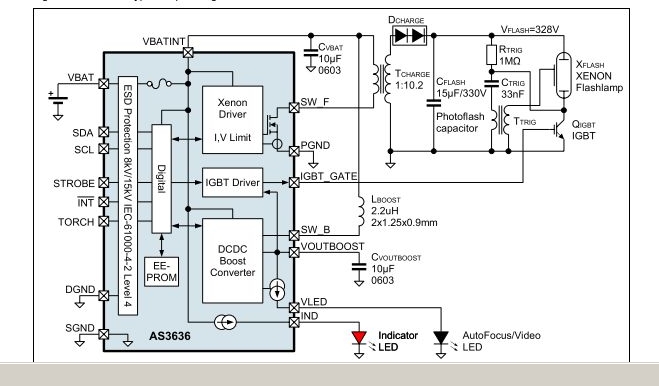
The AS3636 is a highly integrated photoflash charger that includes an IGBT driver, an inductive DC-DC boost autofocus/video LED driver, an indicator LED driver, and incorporates system-level ESD protection. The AS3636 is designed for efficient photoflash charging applications, providing a...
The electromagnetic RBI timer features a simple structure, is cost-effective, and is commonly utilized in high school physics experiments. However, a significant drawback of the electromagnetic RBI timer is the substantial errors it produces during experiments. This issue arises...
The construction LED circuit illustrated in the figure requires manual power. Once powered, the light will blink to alert individuals to pay attention to safety. The circuit is designed to enhance safety awareness in construction environments by utilizing a blinking...
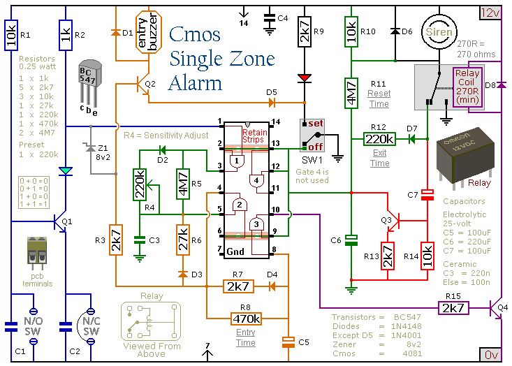
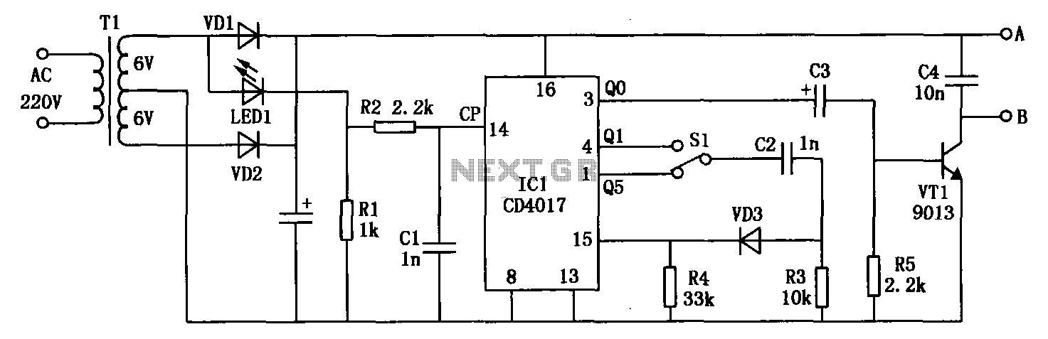
This circuit features automatic exit and entry delays, a timed bell cut-off, and a system reset. It accommodates both normally-open and normally-closed switches, making it compatible with various input devices such as pressure mats, magnetic reed contacts, foil tape,...
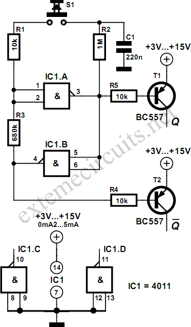
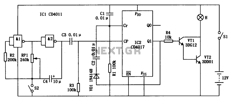
Using just two NAND or inverter gates, it is possible to build a D-type (or toggle) flip-flop with a push-button input. At power-up, the output of gate N2 is at a logical 1, ensuring that transistor T2 is switched...
The disadvantage of infrared or wireless remote control is that the remote transmitter is often misplaced. This circuit design offers a way to control ... This circuit design addresses the common issue of misplaced remote transmitters in infrared or wireless...
Warning: include(partials/cookie-banner.php): Failed to open stream: Permission denied in /var/www/html/nextgr/view-circuit.php on line 713
Warning: include(): Failed opening 'partials/cookie-banner.php' for inclusion (include_path='.:/usr/share/php') in /var/www/html/nextgr/view-circuit.php on line 713