
Resistive Sensor Head (A2053) Manual
 Manual")
You can use the A2053 with the Guage, Thermometer, or Flowmete r. For examples of the A2053 in action, see the Examples section. Figure 2: RTD Head (A2053A) with Enclosure. Connectors 1 through 4 are marked in numberals the box itself. Pin 1 of each connector is at the left end. Connector 4, for RTD 11, is left open in the A2053A. The resistive sensor channel numbers are marked in black numerals around the outside of the box. The RTD Head (A2053A), for example, connects to 1000- © RTDs and measures their resistance with 0. 1- © precision over the range 860 © to 1160 ©. With the help of a calibration program we can use the A2053A to calibrate 1000- © RTDs with 0. 1 °C accuracy. The Strain Guage Head (A2053S) connects to up to eleven 120- © strain guages and measures their resistance with precision 0. 01 © over the range 110 © to 130 ©. The A2053 connects to each of its sensors with a twisted pair of insulated, stranded copper wires. The resistance of these wires adds to the resistance of the sensor. If the sensor is a 1000- © RTD, a 10-m cable made out of twisted pairs pulled from a CAT-5 cable adds a constant +0.
5 °C offset to the apparant temperature of the resistor. The resistance of the wires is roughly 1 © per 10 m. Because the resistance of such wires does not vary significantly with temperature, a one-point calibration of each sensor is sufficient to remove the effect of the wires. Instead of running current continuously through the sensors, or using a Wheatstone Bridge to compensate for various electrical and thermal errors, the A2053 runs a small current through the sensor for a few tens of milliseconds.
Because the A2053 is connected to a LWDAQ, we can digitize this voltage, display it on the screen, and take its average value. Once we have obtained this average value, we instruct the A2053 to run the same current through the bottom reference resistor on its circuit.
With our 1000- © RTDs, we use a 1060- © resistor, which corresponds to a perfect 1000- © RTD at 15. 38 °C. We record the voltage again, then select the top reference resistor. For the 1000- © RTDs, this resistor is 1100 ©, corresponding to 25. 69 °C. We now interpolate between the top and bottom references to obtain the resistance of the sensor. In other words: the accuracy of the A2053 is contained in its precision resistors. Precision resistors are stable and inexpensive. They are small, rugged, and we can put them right next to our measurement circuits. The absolute accuracy of our RTD Head (A2053) is better than 50 mK, which is far less than the accuracy of the sensors we use. In addition to resistance measurement, all versions of the A2053 provide a 15-V heating connection to any one of the sensors.
Heating the sensors allows us to measure the cool-down time constant of the sensor in, for example, a pipe with flowing gas, and thus deduce the gas flow rate. The A2053F uses the heater to measure gas flow rate, as we describe here. The A2053 mounts to a flat metal surface with four M6 bolts. The same bolts hold the A2053 circuit board to the top face of its enclosure. The drawing below shows the locations of the mounting holes. Each hole should be M6 threaded and at least 7 mm deep. Allow at least 40 mm height for the enclosure and its electrical connections. All versions of the A2053 connect to their eleven sensors through two eight-way plugs, one four-way plug, and one two-way 0.
1" footprint that we usually leave unloaded to allow you to put a sensor right on the circuit board. Two wires connect to each sensors. The table below gives the LWDAQ element number corresponding to each pair of sensor connector pins. For an annotated photograph, see here. The LWDAQ Flowmeter instrument, however, takes samples from a single RTD sensor for several seconds at a time without sampling the reference channels, and is unable to keep track of the offsets that grow in its EL2244CS op-amps during the measurement. We discovered this offset problem only after we had made several hundred A2053A boards with the EL2244CS.
The A2053F is identical to the A2053A, but its three EL2244CS op-amps are replaced with three OPA2277UA op-amps in the same SOP-8 package. Therefore, the A2053F can be used as a Thermometer, but the A2053A does not perform well as a Flowmeter.
The connectors used on the A2053 (as well as other assemblies like the A2044) come from the C-Grid family made by Molex-Waldom. Do not confuse the C-Grid family with the C-Grid III family. Connectors from these two families do not mate together. The C-Grid plugs are single-row headers with pins on a 0. 1-inch pitch. Each plug is enclosed in a plastic shroud. The shroud provides a keeper for a latch on the mating socket. The table below gives the Molex-Waldom and Digi-Key part numbers for C-Grid plugs, receptacles, and crimp terminals we use in our assemblies.
We strip a couple of millimeters of insulation off each sensor wire and crimp to each wire a female terminal. There are two crimps on each terminal. One should crimp the wire and the other should crimp the wire insulation. We like to use gold-plated crimps, but if you are going to connect your sensors only once, tin-plated crimps are just as good, and less expensive.
When we have the terminals on the wires, we push the terminals into a receptacle. They lock in place. We can remove them again with the help of a pin. The receptacle itself can provide a locking latch and polarization, or it can be without polarization and without the locking latch. When you have plenty of space to grab the connectors when you want to remove them, we recommend the locking receptacles.
But when there is little space for your fingers, you can use the receptacle without the latch. The disadvantate of the connector without a latch is that it does not provide polarization either, so you can plug it in the wrong way around. You must look at the triangle in the receptacle face and match this up with pin one on the plug. When we crimp our terminals, we like to use the manufacturer`s crimp tool (part number 11-01-0209). But we can also get the job done with a pair of needle-nosed pliers and a little more time and effort.
With adjustments to its reference resistors, the A2053 can be used with any resistive sensor. We obtain best performance with sensors of resistance between 100 © and 1M © where the resistance of the sensor varies by only ±10% over the measurement range. A 1000- © RTD has nominal resistance 1 k © at 0 C. Its resistance increases by approximately 4 ©/C. The combined resistance of the wires leading to a sensor adds to the resistance of the sensor itself, causing an increase in measured temperature of 0.
25 C/ ©. Example: We observed a 50 mK/m increase in measured temperature with our standard stranded-core twisted pair cables. The longest connection to an RTD in ATLAS is nearly five meters, which introduces an increase in absolute temperature measurement of 0.
25 C. But the ATLAS temperature sensors will be calibrated a 20 C, thus removing any absolute error in the error in the absolute temperature measurement, either due to cable resistance or the sensor itself. Our ATLAS temperature sensors are accurate to ±0. 3 C at 0 C, so the error due to connecting wire resistance is comparable to the error due to the sensor itself.
Furthermore, if we know the length of the cable, we can calculate and remove the effect of its resistance. The dominant application of the A2053 so far has been the A2053A with 1000- © RTDs in ceramic packages with radial steel wires.
In 2004, we bought five hundred RTDs with 300-mm teflon-insulated leads from Enercorp for $5 each. We installed these in the ATLAS detector. In 2008 we bought one hundred RTDs with short, tin-plated steel leads for $2 each. Most RTD leads are steel, and so must be tinned with the help of acid flux before solderin. (See solder joints for details of soldering steel wires. ) Another source of radial-wire RTDs is Omega Engineering, which sells radial-lead 100- © RTDs for $1 each in packages of 100, or 1000- © RTDs for $1. 50 each. At Digi-Key you will find surface-mount 1000- © RTDs and radial-wire 100- © RTDs. To determine the command word that will implement a particular operation on the A2053, write out sixteen bits in a row, starting with bit sixteen (DC16) on the left, and ending with bit one (DC1) on the right.
Set each bit to zero or one as you require. The left-most four bits form the most significant nibble of the sixteen-bit command word. The right-most four bits are the least significant nibble. Translate each nibble into a hex digit, and you have the hex version of the command word. The T1 through T11 bits select Sensor 1 through 11. The HEAT bit applies 15 V to the selected sensor or sensors, heating one or all of them. Each heated sensor consumes 15 mA from the +15 V supply, and receives 200 mW of heating power. The WAKE bit wakes up the board by turning on the ±15 V supplies. The TB and TT bits select the bottom temperature reference resistor and the top temperature reference resistor respectively. The LB bit enables the logic loop-back driver, and is used by a LWDAQ Driver`s loop job. Example: To select the top temperature reference, we set the following bits: TT (DC6) and WAKE (DC8).
All other bits should be cleared. We compose the following binary number: 0000 0000 1010 0000, which translates to $00A0 (our symbol for hexadecimal numbers is "$"). To heat the same sensor we transmit $02A0. The A2053 does not respond correctly to the loop job. The loop time we measure with an A2053 is always 0 ns because the A2053 drives R LO when we send it the command that usually sets up a device for loop-back of T.
You will find the schematic of the Sensor readout circuit here. The schematic gives the component values for the A2053A, which reads 1000- © RTDs. Resistor R25 sets the current flowing down out of U16-1 (the collector of the current source transistor), along K+ (the current does not go into Q18, because Q18 is the heater, and we assume it`s turned off), and so to all the sensors via the common K+ connection. But the current flows through only the one sensor whose selection switch (these are the mosfets Q5. Q17) is turned on. The voltage on K+ is the voltage developed across the selected sensor when the measurement current flows through it.
When R25 is 2 k ©, the current is 350 A. Across a 1000- © resistor, this current develops a voltage of 350 mV. 🔗 External reference
Related Circuits
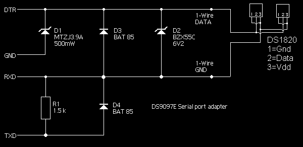
A DS18S20-based serial port temperature sensor has been developed for connection to the USB port of an Asus WL-500gp v2. The temperature sensor functions correctly when directly connected to a PC's serial port; however, issues arise when attempting to...
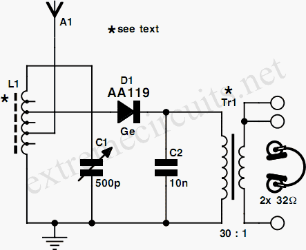
When examining construction notes for building vintage detector-type radios, the specified headphones typically have an impedance of 2 G—2000. In contrast, modern headphones generally have a lower impedance of 2 G—32, which makes them unsuitable for such designs. However,...
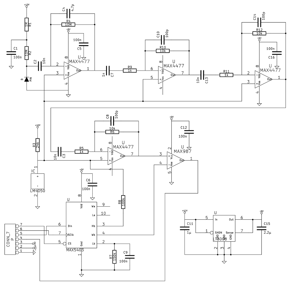
A noteworthy application note from Maxim detailed a gamma-photon detector utilizing a standard PIN diode as its sensing element. The circuit design appeared straightforward, prompting the decision to construct it, as having multiple measurement instruments is always beneficial. The gamma-photon...
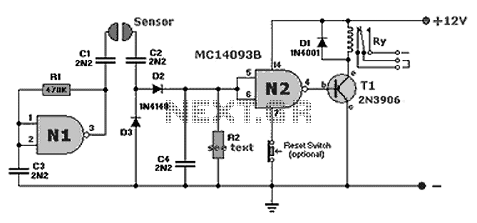
A compact fluid (water) sensor circuit that activates a relay for various applications. Additionally, a printed circuit board (PCB) is not necessary due to the small size of the circuit. The fluid sensor circuit is designed to detect the presence...
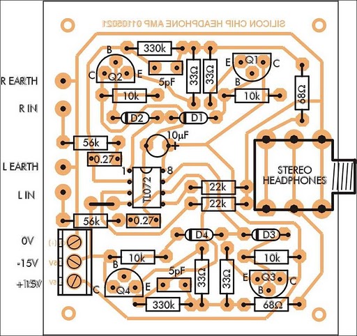
In addition to its primary function as a headphone amplifier, this circuit can be utilized for various applications requiring a wide bandwidth low-power amplifier. It is designed around an operational amplifier (op-amp), with its output current enhanced by a...
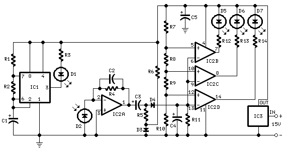
This circuit assists in parking a car near a garage wall by providing distance alerts. LED D7 illuminates when the bumper-wall distance is approximately 20 cm. When the distance decreases to about 10 cm, both D7 and D6 illuminate,...