
Diode Radio For Low Impedance Headphones
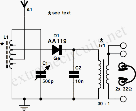
The design of a vintage detector radio requires careful consideration of component specifications, particularly the impedance of the headphones used. The traditional specification of 2000 ohms (2 G) for headphones is crucial for optimal performance, as lower impedance headphones (32 ohms) may not effectively match the circuit's requirements. To adapt modern headphones, a transformer from a mains adapter can be employed. This transformer should feature multiple output voltage taps, allowing for flexibility in impedance matching.
The antenna coil plays a vital role in the radio's reception capability. Constructed on a ferrite rod, the coil's dimensions and the number of turns are specifically chosen to enhance medium wave reception. The presence of tap points at intervals of 10 turns enables fine-tuning of the antenna's performance, allowing the user to select the most effective configuration for their environment.
In addition to the antenna coil, the external aerial significantly impacts reception quality. Utilizing metal infrastructure, such as guttering and pipes, as an aerial can enhance signal capture, provided these elements are not grounded. This setup takes advantage of the conductive properties of metal to improve reception, particularly in areas with strong broadcast signals.
Overall, this circuit design illustrates the adaptability of modern components for use in traditional radio applications, emphasizing the importance of impedance matching and the strategic use of available materials to optimize performance.If you ever look at construction notes for building old detector type radios the type of headphones specified always have an impedance of 2 G— 2000. Nowadays the most commonly available headphones have an impedance of 2 G— 32 , this relatively low value makes them unsuitable for such a design.
However, with a bit of crafty transformation the se headphones can be used in just such a design. To adapt them, you will need a transformer taken from a mains adapter unit, the type that has a switchable output voltage (3/4. 5/6/9/12 V) without the rectifying diodes and capacitor. Using the different taps of this type of transformer it is possible to optimize the impedance match. For the diode radio (any germanium diode is suitable in this design) the key to success is correct impedance matching so that none of the received signal energy is lost.
The antenna coil on the 10 mm diameter by 100 mm long ferrite rod is made up of 60 turns with a tap point at every 10 turns; this is suitable for medium wave reception. If a long external aerial is used it should be connected to a lower tap point to reduce its damping effect on the circuit.
You can experiment with all the available tapping points tond the best reception. With such a simple radio design, the external aerial will have a big in‚uence on its performance. If your house has metal guttering and rain water pipes, it will be possible to use these as an aerial, as long as they are not directly connected to earth. Those who live in the vicinity of a broadcast transmitter may be able to connect a loudspeaker directly to the output or if the volume is too low, why not try connecting the active speaker system from your PC
🔗 External reference
Related Circuits
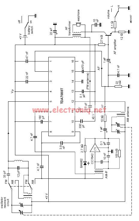
The TDA7088 incorporates a frequency-locked loop (FLL) system with an intermediate frequency (IF) of approximately 70 kHz. This circuit can be powered using a 3-volt battery cell or a regulated power supply. The TDA7088 is designed for use in various...
A newcomer to electronics has recently acquired several electromechanical seven-segment vane displays and seeks assistance. Electromechanical seven-segment vane displays are devices commonly used for visual representation of numerical data. They consist of a series of segments arranged in a figure-eight...
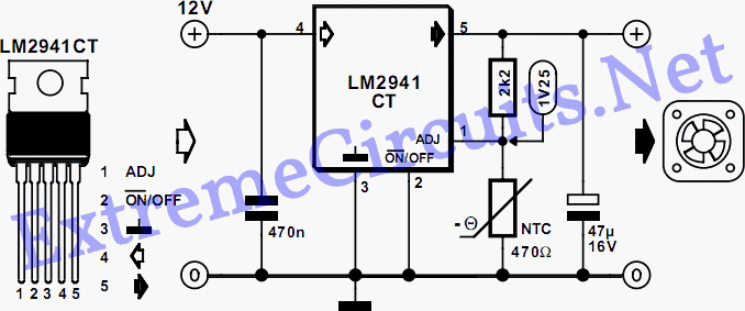
The fan operates continuously in many PCs, which may not be necessary. A simple controller circuit can adjust the fan speed based on demand. This not only conserves energy but also minimizes noise irritation from the fan. Only three...
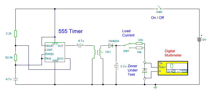
This circuit utilizes a single 555 Timer IC and a small transformer to generate high voltage for testing zener diodes with voltage ratings up to 50VDC. The 555 Timer is configured in astable mode, with the output from pin...
Rl sets the comparison level. At comparison, the photodiode has less than 5 mV across it, decreasing dark current by an order of magnitude. More: IC = LM 111/211/311. In this circuit description, the resistor Rl plays a crucial role...

The circuit of the transmitter is depicted in Figure 1, showcasing its simplicity. The initial stage is the oscillator, which is tuned using a variable capacitor. To select an unused frequency, adjust C3 carefully until background noise ceases (the...