Restoration of a Yamaha A-760 vintage integrated amplifier
9,993
A matching Yamaha T-760 tuner is visually appealing and sounds excellent when paired with the A-760 amplifier. The total cost was 6 euros, plus 16.20 euros for shipping from Austria. On December 31, 2006, an X2 RFI capacitor was replaced, all switches and potentiometers were cleaned with De-Oxit, and the bias, offset, and power supply voltages were rechecked and adjusted according to the service manual. The circuitry was visually inspected, resulting in a setup ready for serious listening with a pair of Yamaha Pianocraft bookshelf speakers, performing almost like new. On December 24, 2006, a burned lamp was replaced with a couple of resistors, a diode, and a white LED. The power transistors were checked, the amplifier was cleaned, powered on, and it functioned properly. On December 23, 2006, the cover was opened to identify the burned components, and pictures were taken. A quick visual check of other components did not reveal any obvious damage. The amplifier was acquired that morning from the previous owner, along with the original owner's manual, with a warning about smoke emitted during the burn incident, leaving a lingering odor. The Yamaha A-760 is an 80W/channel stereo integrated amplifier manufactured in Japan and sold globally only in 1981, with a European model in possession. The A-760 and its larger counterpart, the A-960 (100W/channel), are successors to the renowned CA-1000/CA-1010/CA-2010 integrated amplifiers. Yamaha marketed the A-760 and A-960 featuring a new "X" power supply, which adjusted the line voltage to the output stage's requirements, a technology also used in their R-1000 and R-2000 receivers, and in the high-end M-60 and B-6 power amplifiers. Bob Carver held a patent for similar technology and threatened Yamaha with a patent infringement lawsuit. In 1982, Yamaha released revised models, the A-760II and A-960II, which presumably did not incorporate the "X" power supply. Upon opening the cover, the burned component was evident; the Rifa RFI capacitor had overheated, shorted, and exploded, spilling oil onto surrounding components and the printed circuit board, creating a strong burnt oil smell, indicative of a catastrophic failure. A burned fuse was also visible. The blue component next to the capacitor is a Yamaha-specific part, now rare. The output stage is centrally located. Marantz engineers utilized a single heatsink parallel to the front panel, while Yamaha engineers opted for two separate heatsinks (one for each channel) at right angles to the front panel. The intricate wiring and numerous components reflect a sophisticated and costly amplifier design, especially when compared to the Marantz PM450. Both amplifiers achieve their power ratings using a single complementary pair per channel; however, the Yamaha design is more complex to deliver an additional 40-50W RMS at lower distortion levels. The primary "X" power circuit is situated to the right of the large transformer, employing an opto-coupler to control a triac circuit that activates an extra winding in the transformer primary circuit. The RIAA preamplifier is built around a JRC NJM4559D dual op-amp, which is a 2V/us slew rate variant of the 4558. Each half of the op-amp is preceded by a pair of low-noise, high-transconductance SK170 N-channel JFETs in a differential amplifier configuration. The 4559 also has its own voltage regulation, located in the lower right section of the board. A high-quality selector switch enables the choice between MM or MC circuits at the top right, alongside two similar input and record-out selector switches on the left. Each channel of the power output stage is driven by a pair of bipolar complementary transistors, Toshiba 2SB755/2SD845, mounted on a substantial extruded aluminum heatsink.A matching Yamaha T-760 tuner. It sounds (and obviously looks) great with the A-760. The cost was 6 euros, plus 16, 20 euros for shipping from Austria. 31-12-2006: Put back an X2 RFI capacitor, cleaned all the switches and pots with De-Oxit, re-checked and readjusted bias and offset and power supply voltages per the service manual, visually re-inspected the circuitry, and now it`s setup for some serious listening with a pair of Yamaha Pianocraft bookshelves. So far performing (and almost looking) like new! 24-12-2006: Replaced a burned lamp with a couple of resistors, a diode and a white LED. Checked the power transistors, cleaned up the amp, fired it up and it works! 23-12-2006: Opened the cover, found out what was burned, took some pictures. See below. A quick visual check of the other components does not reveal any obvious damage. 23-12-2006: got the amplifier this morning, directly from the previous owner, with the original owner`s manual. Was warned about the smoke that came out of the amp when it burned. It does smell bad! The Yamaha A-760 is a stereo 80W/ch. integrated amplifier manufactured in Japan by Yamaha and sold worldwide only in 1981. I have the European model. The A-760 and its slightly bigger brother (100W/ch. ) the A-960 are the successors to the renowned CA-1000/CA-1010/CA-2010 integrated amplifiers. Yamaha advertised the A-760 and A-960 as featuring a new "X" power supply, which would adjust the power supply`s line voltage to the level required by the output stage; Yamaha used the same technology in their R-1000 and R-2000 receivers, and in the TOTL M-60 and B-6 ("pyramid" design) power amplifiers.
Apparently Bob Carver held a patent for exactly this sort of technology and threatened Yamaha with a patent infringement lawsuit. In 1982 Yamaha came out with revised A-760II and A-960II models that I assume did not feature an "X" power supply anymore.
Upon opening the cover, the "burned" part was pretty obvious. The Rifa RFI capacitor had overheated, shorted and exploded, spilling oil over the surrounding components and printed circuit board. The smell of burned oil was very strong. Ahem. a catastrophic failure. Note the burned fuse - not really surprising! The spilled oil is visible too. The blue component to the left of the capacitor is a Yamaha-specific part, very much unobtanium nowadays.
Ouch! Output stage in middle. The Marantz engineers used a single heatsink running parallel to the front panel, whereas Yamaha engineers decided on two separate heatsinks (one per channel) at right angles to the front panel. The wiring and the sheer number of components belie an expensive and complex amplifier circuit, and I can`t help comparing the Yamaha internals to those of the Marantz PM450 on which I was working just a few days ago.
Both amplifiers achieve their power ratings with a single complementary pair per channel, but to get an extra 40~50W RMS at a slightly lower distortion, the Yamaha engineers resorted to a very complex design. The primary "X" Power circuit can be seen to the right of the massive transformer. An opto-coupler is used to control a triac circuit that enables an extra winding in the transformer primary circuit.
The RIAA preamp is based on a JRC NJM4559D (2V/us slew rate variant of the 4558) dual op-amp, with each half preceded by a pair of low noise high transconductance SK170 N-channel JFETs in a differential amplifier configuration. The 4559 also gets its own voltage regulation (seen on the lower right part of the board). Note the high-quality selector switch that allows one to choose either the MM or MC circuit on the top right, and the two similar input and rec out selector switches on the left.
Each channel of the power output stage is driven by a pair of bipolar complementary transistors Toshiba 2SB755/2SD845 mounted on a massive extruded aluminium heatsink: The 🔗 External reference
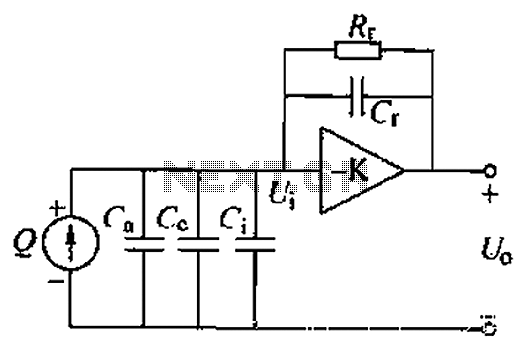
A charge amplifier is an effective device for measuring punch hits. This amplifier utilizes a negative feedback capacitor in conjunction with a high-gain operational amplifier. The amplifier operates with minimal shunt, relying primarily on the feedback capacitor's charge (q...
Can be directly connected to CD players, tuners and tape recorders.
The circuit described above can be interfaced directly with various audio devices such as CD players, tuners, and tape recorders. This indicates that the circuit is designed to handle...
This amplifier features high fidelity (Hi-Fi), high sensitivity, low power consumption, and low distortion, making it an excellent choice for high fidelity sound systems. The process of creating a printed circuit board (PCB) can be accomplished in a few...
This is a standard amplifier based on LM 1875. It can deliver 20 W, with an 8 Ω speaker and 60V power supply even 30 W.
The capacitors C4 and C5 should preferably be as close to the IC down....
This document provides a circuit diagram of a car stereo. It includes a circuit diagram of a Class B 15 Watts audio amplifier designed using a dual op-amp and a transistor. The 15 W Class B audio amplifier circuit...
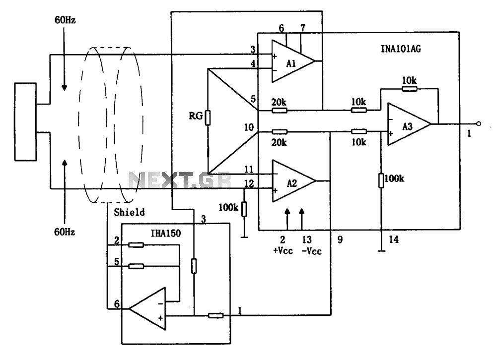
The circuit diagram illustrates a hum elimination instrument amplifier circuit. The amplifier stages A1 and A2 utilize the integrated operational amplifier INA101, followed by stage A3 which employs the INA105. A feedback circuit is incorporated to reduce the power...
We use cookies to enhance your experience, analyze traffic, and serve personalized ads.
By clicking "Accept", you agree to our use of cookies.
Learn more