
rf amplifier with op amp
The operational amplifier (op-amp) serves as a fundamental building block in analog electronic circuits. The 741 and 301 series of op-amps have become staples in the field due to their reliability and ease of use. The basic configuration of an op-amp allows for various gain settings through feedback resistors, making them adaptable for numerous applications.
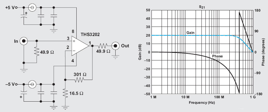
In RF applications, the THS3202 op-amp exemplifies modern advancements, offering high-frequency performance that extends into the GHz range. This capability is essential for applications requiring fast signal processing and high fidelity. The circuit configuration described utilizes a flat gain of 20 dB, which is critical for maintaining signal integrity across a broad frequency spectrum up to 200 MHz.
The input and output impedance are crucial in RF designs, as they affect how the circuit interacts with other components. The 49.9 Ohm resistor serves to match the impedance, minimizing reflections and maximizing power transfer. The gain setting, determined by the resistors of 301 Ohm and 5.16 Ohm, allows for precise control over the amplification factor, which can be essential in maintaining signal quality.
The total gain of 40 dB achieved by the circuit is noteworthy, as it illustrates the potential for significant amplification in RF applications. The feedback mechanism is vital for stability and performance, and the selection of resistor values directly influences the op-amp's behavior. Furthermore, the inclusion of a 332 Ohm resistor at the ceramic filter point ensures that the termination impedance is correctly set, further enhancing the circuit's performance in handling high-frequency signals.
Overall, the evolution of op-amps like the THS3202 demonstrates the ongoing advancements in semiconductor technology and their implications for modern electronic design, particularly in high-frequency applications.Op-Amp`s right, not wrong title. I know the op amp is approximately 20 years ago, at age 741/301 series, an easy calculation (gain calculation), affordability, and simplicity of construction makes a very interesting op-amp. So many of the implementation of the op-amp, and even had time to try to build the "op-amp based computer".
Almost all can be built with op-amp, except for RF. But that first, reversing the progress of semiconductor technology this condition, a few years back the manufacturers have managed to build an op-amp with a working frequency up to GHz. An article from Texas Instrument by Bruce Carter describes the application of op-amp (THS3202) on the rf circuit.
Above circuit provides flat gain of 20dB in the range up to 200MHz. Terminasi input and output impedance is determined by the resistor 49. 9Ohm. Strengthening the voltage is determined by resistor 301 Ohm / 5. 16 Ohm. Choice of reinforcement could be done as to determine the op-amp gain. The circuit above provides 40dB gain (2 x 20dB). Consider the provision of value as a determinant of the gain resistor (feedback). Note also the termination impedance at the point-B0 SFELA10M7GA00 ceramic filter a 332 Ohm resistor is applied there. 🔗 External reference
Related Circuits

The main component of the circuit has been achieved using an integrated circuit (IC) with a significant number of bulk components, primarily capacitors. The internal circuit is designed to output from the differential amplifier using a PNP unipolar configuration,...
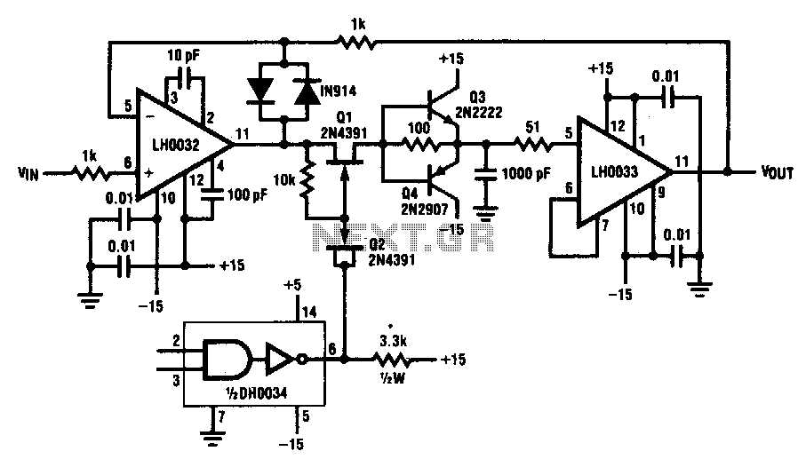
This circuit demonstrates a 10 V acquisition time of 900 ns with 0% accuracy and a droop rate of only 100 µV/ms at an ambient temperature of 25°C. A faster acquisition time can be achieved by using a smaller...
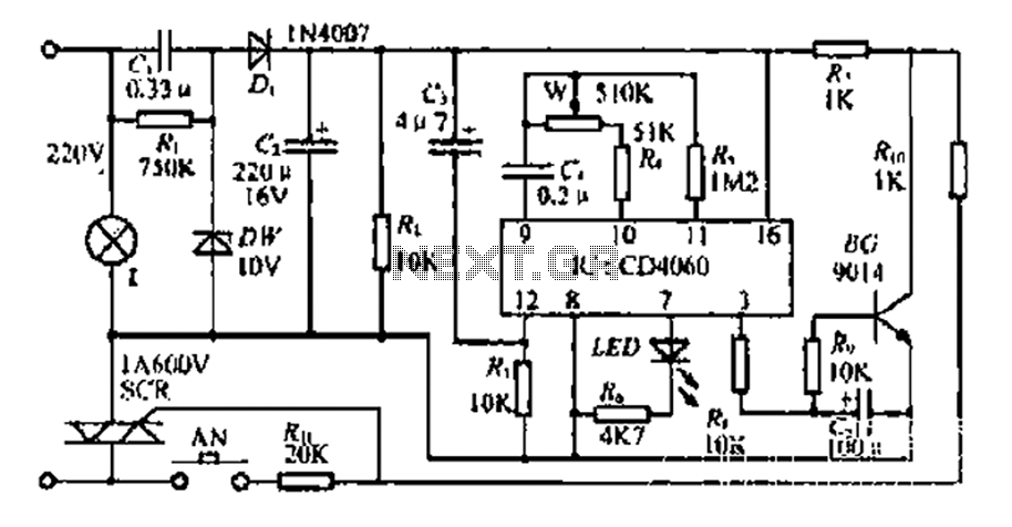
The circuit includes a CD4 component with a connection of 16 feet for the Vcc terminal, 8 feet for the ground, 12 feet for the reset terminal, 7 feet for the Qt end, and 3 feet for the Q...
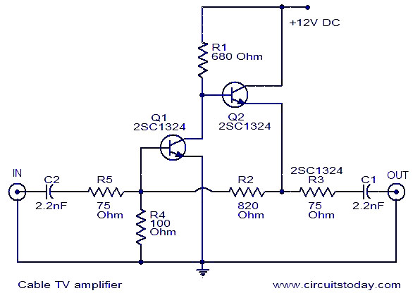
This is a simple cable TV amplifier using two transistors. The amplifier circuit is designed for cable TV systems utilizing 75 Ohm coaxial cables and is effective up to 150 MHz. Transistor T1 is responsible for amplification, providing up...

These circuits are useful for video applications up to 10 MHz. The 3.3-pF capacitors serve as compensation capacitors. The capacitors connected to pins 7 and 4 act as bypass capacitors to prevent self-oscillations. Figure 76-18(a) illustrates a non-inverting configuration,...
A Class-A audio amplifier is known for its high power consumption; however, its simplicity is appealing when ample power is available. This circuit features a Darlington transistor designed for use with a 5-volt power supply. It is important to...