
Cable TV amplifier

The described cable TV amplifier circuit employs a straightforward design based on two transistors, which are critical components in achieving the desired amplification. The first transistor, designated as T1, serves as the primary amplifying stage, capable of providing a gain of up to 20 dB. This level of amplification is particularly beneficial for cable television applications, where maintaining signal integrity is essential for clear audio and video output. The second transistor, T2, is configured as an emitter follower. This configuration is advantageous as it increases the current gain without significantly affecting the voltage gain, thus ensuring that the output signal can drive subsequent stages or loads effectively.
The circuit is optimized for use with 75 Ohm coaxial cables, which are standard in many cable TV installations. The operational frequency range of the amplifier is specified up to 150 MHz, making it suitable for typical cable television frequencies. The suggestion to utilize the 2SC2570 transistors is noteworthy, as this component is known for its low noise characteristics, which can enhance the overall performance of the amplifier by minimizing interference in the audio and video signals.
In terms of additional modifications, the inclusion of a 6-turn close-wound air core coil can further refine the circuit's performance. This coil, constructed from 18 SWG super enameled copper wire, can be strategically placed to improve signal filtering and stability. Proper placement between the capacitor (C2) and resistor (R5) junction and ground may help in reducing unwanted noise and enhancing the quality of the amplified signal.
Questions regarding the circuit's application in Wi-Fi signal amplification highlight the need for careful consideration of frequency ranges and component specifications. The original design is not tailored for the 2.4 to 2.5 GHz frequency band, which is typical for Wi-Fi signals. Using this circuit for such purposes may not yield the desired results, especially when attempting to extend coverage over a significant distance, such as 10 km. The performance of multiple circuits in series for Wi-Fi amplification would require extensive testing and potentially different design considerations to ensure adequate gain and stability at higher frequencies.
Finally, the issue of poor picture quality on a TV card when another television is in use suggests that the amplifier's gain may not be sufficient to handle multiple loads simultaneously. This scenario emphasizes the importance of ensuring adequate gain to maintain signal quality across all connected devices, particularly in shared setups where multiple devices may draw from the same signal source.This is a very simple cable TV amplifier using two transistors. This amplifier circuit is most suitable for cable TV systems using 75 Ohm coaxial cables and works fine up to 150MHz. Transistor T1 performs the job of amplification. Up to 20dB gain can be expected from the circuit. T2 is wired as an emitter follower to increase current gain. Hi Chary try using 2SC2570 for both the transistors. You can find the difference in the noisey channels both in audio and video or atleast in audio (the frying noise with audio will get reduced). Finally you may try a 6 turns close wound air core coil of 6mm dia with 18 SWG super enameled copper wire, between C2, R5 junction and ground.
I cant getting any changes in quality of picture, and I am using Transformer with rectifier and capacitor for providing 12v supply. please solve my problem, I wanted to ask whelther this circuit would be ideal to amplify wifi signals around 2.
4 to 2. 5 Ghz. I was working on a project in which i have to spread my wifi signals in 10km radius, i can use this circuit in series to amplify signal many many times, ill use atleast 15 of these circuits in series Actually, I have a Television and Computer TV Card in my home. When My dad watch TV, then my TV Card display poor quality Picture. Otherwise it is good. May be it is happennig for less line gain when running two sets (Television+TV Card). 🔗 External reference
Related Circuits
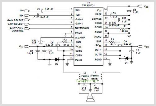
The TPA3112D1 is a 25-W efficient Class-D audio power amplifier designed for driving a bridge-tied speaker. It incorporates advanced EMI suppression technology, allowing the use of cost-effective ferrite bead filters at the outputs while complying with EMC requirements. The...
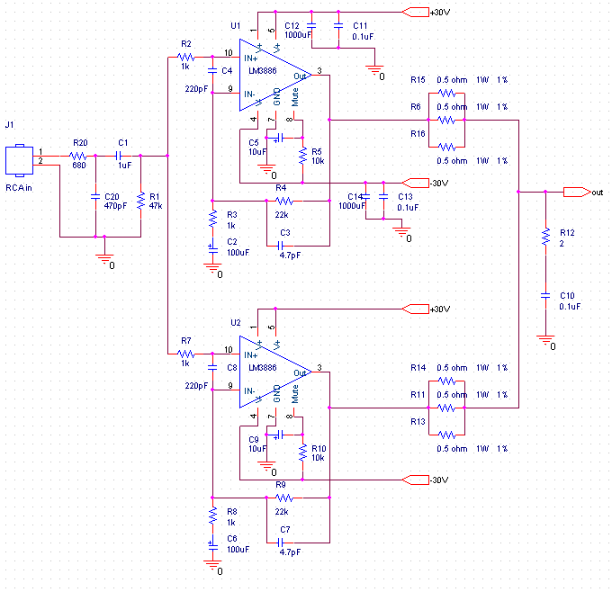
This audio amplifier design utilizes two LM3886 chips per channel in a parallel configuration, based on the PA100 parallel amplifier detailed in National Semiconductor's application note AN1192. The amplifier can deliver approximately 50W into an 8-ohm speaker and 100W...
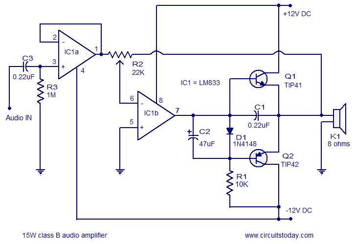
A 15 Watts Class B audio amplifier circuit is designed using a dual op-amp LM833. The schematic diagram is provided, and a potentiometer allows for volume control. The 15 Watts Class B audio amplifier circuit utilizes the LM833 dual operational...
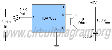
Schematic diagram and description of a 2-watt audio amplifier circuit using the TDA7052 amplifier IC. This is a very simple audio amplifier circuit. The 2-watt audio amplifier circuit utilizing the TDA7052 integrated circuit (IC) is designed for basic audio amplification...
Tiny, portable guitar amplifiers are beneficial for practice while on the go and in bedroom or living room environments. Typically, they can be powered by batteries and include a headphone output. This project incorporates an FET input circuit with...
In addition to its primary function as a headphone amplifier, this circuit is applicable in various scenarios requiring a wide bandwidth low power amplifier. It utilizes an operational amplifier (op-amp) with its output current enhanced by a pair of...