
RF Mixer Circuit

Mixers play a crucial role in communication systems, particularly in radio frequency (RF) applications. They are essential for frequency conversion, allowing signals to be shifted to different frequency bands for processing. In a typical RF application, the mixer combines an incoming RF signal with a local oscillator signal. The result is an intermediate frequency (IF) signal that is easier to filter and amplify.
The design of a mixer can vary greatly depending on the application requirements. For instance, a diode mixer, which is the simplest type, typically consists of a single diode connected to the input and output ports along with tank circuits that help in selecting the desired frequency components. The diode's nonlinear characteristics allow it to mix the RF and local oscillator signals effectively.
In contrast, transistor mixers can offer improved performance in terms of gain and noise figure. They often utilize bipolar junction transistors (BJTs) or field-effect transistors (FETs) to achieve better signal handling capabilities. The transistor mixer can be configured in various ways, such as using balanced or unbalanced arrangements, to optimize performance based on the specific application.
Vacuum tube mixers, although less common today, are still used in some high-frequency applications due to their ability to handle high power levels and maintain linearity over a wide dynamic range. These mixers typically require more complex circuitry and power supply arrangements but can provide superior performance in certain niche applications.
In summary, mixers are versatile components used in various electronic circuits to combine signals. Their design can range from simple diode-based configurations to more complex transistor or vacuum tube implementations, each tailored to meet specific performance criteria in communication systems.In the general sense a mixer is basically any circuit that combines two or more circuits or signals into a common output. A more commonly used definition defines a mixer as a nonlinear circuit as one that accepts as its input two different frequencies [F1 & F2] and than outputs between two and four signals: The term non-linear refers to a component which causes a current
to with the application of a voltage, but the current does not change in a linear relationship with the voltage. See Heterodyning. The standard symbol for a mixer, shown in the right side-bar is a circle with an `X` in the center. The diagram also depicts one of the most common uses of a mixer, that is combing a local oscillator with an RF signal to produce an IF signal.
The term mixer describes a function, that of mixing two signals together. So there are a vast number of ways to implement a mixer. The mixers shown on this page include a mixer made from a diode, a transistor mixer, and a vacuum tube mixer. However those are just the component used to provide the nonlinear function, within those three groupings there are even more variations.
There isn`t necessarily a need to design a mixer using discrete components. Mixers are also sold as complete self-contained components, refer here for a lost of Manufacturers of RF Mixers. The circuits shown here are just intended to show a few different circuit variations, and not intended to cover the design of a mixer.
Unbalanced mixers is a style that allows some of the input signal power to pass through to the output. While a single-balanced mixer is configured so the local oscillator, or RF input, cancels and cannot pass through to the output.
However a double balanced mixer has symmetrical paths for both the oscillator and RF inputs, and will have no output if either input signal is not present. A diode mixer is the simplest form of mixer circuit, and uses a diode as the nonlinear device. An example of an unbalanced diode mixer is shown in the right side-bar. This example has tank circuits on each port. 🔗 External reference
Related Circuits
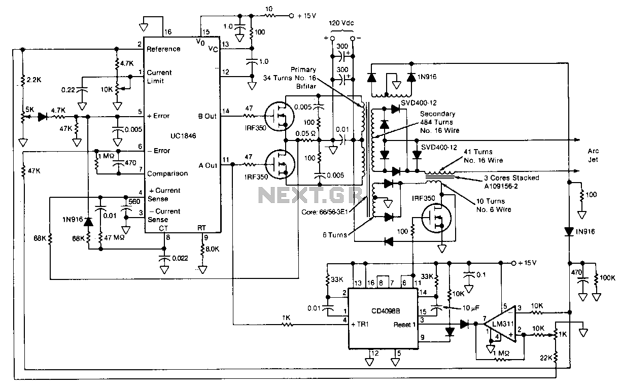
This circuit for starting arc jets and controlling them in steady operation is capable of high power efficiency and can be constructed in a lightweight form. The design comprises a pulse-width-modulated power converter, which is configured in a closed...
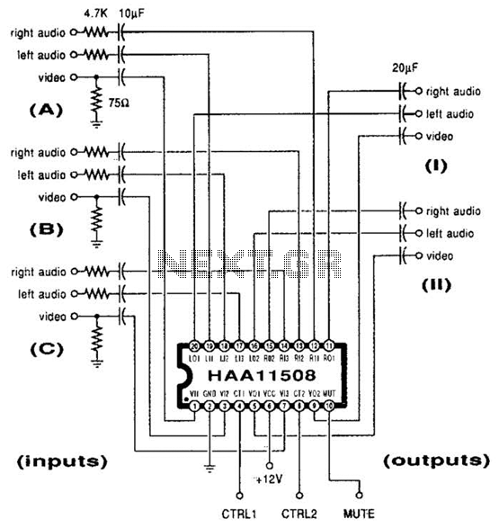
This channel selector selects video and stereo audio from any one of three different sources. The circuit should be constructed on a PC board with plenty of ground plane to minimize noise. The channel selector circuit is designed to facilitate...
This index is organized alphabetically by each word (excluding prepositions). For instance, the "Frost Alarm" will be listed under both "A" and "F". To efficiently locate a circuit, utilize the top index or employ your browser's search feature. In...

When the supply voltage drops below a minimum threshold, it is often advisable to disconnect the supply from the system to prevent poor performance or erratic operation. The circuit presented achieves this with minimal cost, board space, and complexity....
This is an efficient 4-stage stabilized power supply unit designed for testing electronic circuits. It delivers well-regulated and stabilized output, which is crucial for most electronic circuits to function correctly. The circuit includes an audio-visual indicator that activates in...
This infrared alarm barrier is designed to detect individuals passing through doorways, corridors, and small gates. The transmitter emits a beam of infrared light that remains invisible to the human eye. When a person interrupts the light beam, the...