
Simple circuit shuts off system when supply voltage is low

The circuit is designed to provide a reliable method for disconnecting power from a load in response to voltage levels that could lead to suboptimal operation. The LM4041 voltage reference serves as the core component, monitoring the voltage across a resistor (R1) to determine whether the supply voltage remains within acceptable limits. The use of the NPN transistor as a switching element allows for efficient control of the P-channel MOSFET, which acts as the primary switch for the load.
The configuration ensures that in normal conditions, the MOSFET is fully turned on, allowing current to flow to the load. The hysteresis introduced by R4 is crucial for stabilizing the operation of the circuit, preventing rapid switching that could occur near the threshold voltage. This feature enhances the reliability of the circuit by avoiding oscillations that could result from minor fluctuations in voltage.
For applications requiring different shut-off voltages, careful selection of the resistor values R1 and R2 can tailor the circuit to meet specific needs. The design is optimized for low-cost, compact implementations, making it suitable for various electronic applications where voltage monitoring and protection are essential. The maximum supply voltage rating of 30 V offers flexibility for integration into a wide range of systems, ensuring that the circuit can handle various operational scenarios without compromising performance.When supply voltage drops below a minimum threshold, it`s often good practice to disconnect the supply from the system to prevent poor performance or erratic operation. The circuit shown accomplishes this with minimal cost, board space, and complexity ( see the figure ).
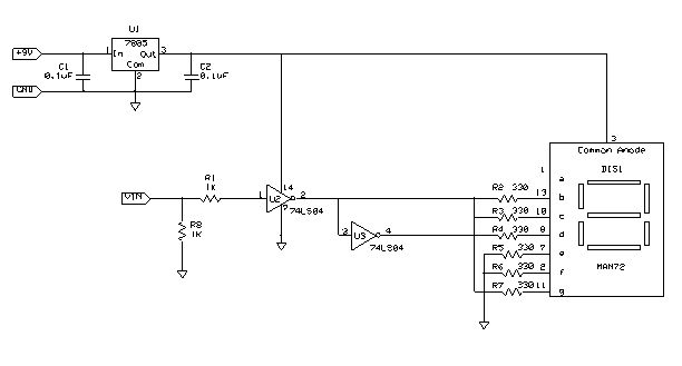
In addition, the active components are available in tiny, SOT-23 packages. IC1 is an LM4041 adjustable voltage reference that serves here as a programmable voltage detector. It does this by operating in an unconventional configuration. Typically, the LM4041 develops a voltage between its positive and negative terminals that forces 1. 24 V between its + and ADJ pins. With R3 in the circuit, however, IC1`s - pin will be near ground when the voltage across R1 is less than 1. 24 V, and about a volt below V+ when the voltage across R1 is greater than 1. 24 V. When the supply voltage is in the normal operating range (above about 4. 6 V in the circuit shown), the voltage across R1 will be greater than 1. 24 V. This pulls the LM4041`s - pin high, turning on the npn, which then turns on the p-channel MOSFET by pulling its gate low.
In this condition, power is supplied to the load through the p-channel device. When the supply voltage drops below the normal operating range, the LM4041`s - pin goes low, turning off the npn and the MOSFET pass device, which removes power from the load. R4 provides hysteresis to avoid supply modulation near the switching threshold. where Vlow is the low-voltage shutoff threshold. By proper choice of R1 and R2, this circuit will work well for shut-off voltages in the range of about 4.
5 to 10 V. The lower limit is determined by the pass FET`s threshold voltage and the upper limit is determined by IC1`s maximum supply-voltage rating. Higher cutoff voltages can be accommodated with minor circuit changes. The maximum supply voltage for the circuit shown is approximately 30 V. 🔗 External reference
Related Circuits

That circuit is based at a technique to remove or neutralize the salt in water, and protect the pipes at home as well as the washing machines or our selves from salt. Its called water softener and its automated...

An integrated power amplifier TDA2040 is used in an OTL (Output Transformer-Less) power amplifier circuit, which operates with a +3V single supply as the working voltage. This circuit has a voltage gain of 30 dB (approximately 32 times magnification),...
The following instructions outline the process for constructing a practical test tool designed for troubleshooting and analyzing digital and microcontroller circuits. The complete assembly and instruction manual can be downloaded from the provided web link: Don's Projects. To begin,...

An automobile permanent magnet alternator can fail, causing headlights to suddenly brighten and then go out while driving at night. The issue may stem from a damaged voltage regulator, leading to voltage spikes. This generator, a JFYJ2102 type (28V/36A)...

CA3600E array transistor pair and a reverse CA3080 operational amplifier are used together to provide precise timing and thresholds for the square wave. A typical static power consumption is 6mW. The CA3600E is a versatile integrated circuit that includes multiple...
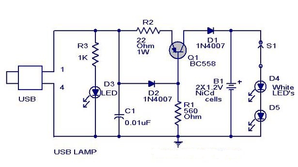
A simple USB-powered lamp designed to illuminate a desktop during power outages. The circuit operates at 5 volts sourced from a USB port. The 5V from the USB is directed through a current-limiting resistor (R2) and a transistor (Q1)....