
RF-Radio Frequency 6
The potentiometer can be installed separately, if des ired, as well as R3 and Zener diode Interference from ignition noise pulse of the engine, it can cause various problems associated with radio communication equipment installed in the car. This circuit improves signal to noise ratio (S / N-ratio) was better, To connected between the output of the detector circuit with the audio input (if high impedance) or region of the impedance between the high dance audio section.
The automatic Gian control circuit also AGC with audio signal is simplest for compress to signal in the Radio receiver. It is ideal for short wave radio receiver used in areas with weak signals. You should adjust the master volume control dress until the desired signal intensity. While tuning the receiver to the station light, then gradually tuned to the power station and adjust the AGC pot until the pressure in the hearing as needed This circuit was designed as an aid to installers and maintainers of video systems.
It is basically a video sync separator (IC1) followed by a LED and buzzer driver (IC2, Q1 & Q2). In use, the device is connected to a video cable and if there is video present, the LED will flash at about 10Hz. If there is no video, the LED flashes briefly every couple of seconds. A buzzer can also be switched in to provide an audible indication. The buzzer is particularly useful when tracing cabling faults or trying to find a correct cable amongst many, where it is difficult to keep an eye on the LED.
Another use for the buzzer option is to provide a video fault indication. For example, it could be inserted in bridging mode, with switch S1 in high impedance mode (position 2) across a video line and set to alarm when there is no video present. If someone pulls out a cable or the video source is powered off, the alarm would sound. IC1 is a standard LM1881 video sync separator circuit and 75 termination can be switched in or out with switch S1a.
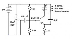
The other pole of the switch, S1b, turns on the power. The composite sync output at pin 1 is low with no video input and it pulses high when composite sync is detected It changes frequency as the incoming voltage, Frequency control. That, from the IC Oscillator NE566. IC phase locked loop circuit is in the nature of Demodulator. The output at Pin 7 and is connected to the IC op amp 741. Which is connected in a manner of Voltage-follower circuit. to the driver IC 566 to work. The voltage passing through the pin 6 of IC op amp, will be entered into a 5-pin of the IC 566. To control the frequency of leg 3 of the IC NE566. the multiplication of frequency equal to R1, C1, R2, C2. For the operation of the circuit stability. Therefore the value of R1 and C1 should be chosen to suit the frequency. Here is the circuit of an excellent direct coupled radio ideal for listening to near by stations. The circuit uses Q1 as a diode detector and first audio amplifier. The detection is across the first emitter base junction which operates as a diode. The base emitter capacitance provides the radio filtering. The resistor R1 is adjusted to obtain the least distortion with consistent volume. Transistors Q2 and Q3 also serve as audio amplifiers Here is the circuit diagram of a simple AM transmitter circuit that can transmit your audios to your backyard.
This circuit is designed with limited the power output to match the FCC regulations and still produces enough amplitude modulation of voice in the medium wave band to satisfy your personal needs. You will love this!. The circuit has two parts, an audio amplifier and a radio frequency oscillator. The oscillator is built around Q1 🔗 External reference
Related Circuits
The circuit is capable of measuring frequencies ranging from 1.5 kHz to 500 kHz by connecting different capacitors, C1 to C6. It can handle a maximum frequency of up to 1 MHz. Transistor T1 serves as the integrator, with...
This circuit accepts positive, negative, or differential control voltages. When the control voltage is zero, the output frequency is also zero. The described circuit functions as a versatile control voltage interface, capable of processing a range of input signals, including...
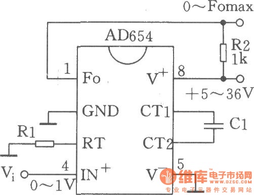
The circuit depicted is a low-cost voltage frequency converter (VFC) utilizing the AD654 component. By connecting the required components, Rl and Cl, as shown in the figure, a functional VFC application circuit can be established. The supply voltage can...
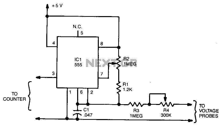
The output frequency from IC pin 3 is determined by the voltage input to pin 6. A standard frequency counter can be used to measure voltages directly over a limited range from 0 to 5 V. In this circuit,...
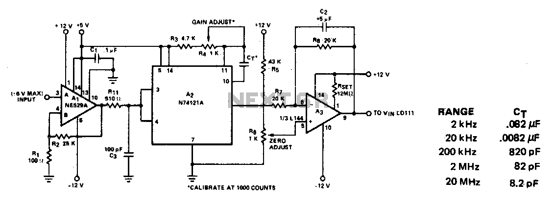
This circuit converts frequency to voltage by taking the average DC value of the pulses from the 74121 monostable multivibrator. The one-shot is triggered by the positive-going AC signal at the input of the 529 comparator. The amplifier acts...
This voltage-to-frequency converter (VFC) circuit utilizes a 555 integrated circuit (IC) and a 741 operational amplifier (op-amp) as its primary components. The circuit is capable of generating oscillations of up to 20 kHz. The voltage-to-frequency converter circuit is designed to...