
voltage to frequency converter with 555
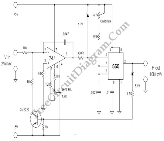
The voltage-to-frequency converter circuit is designed to convert an input voltage into a corresponding frequency output. The configuration employs the 555 timer in astable mode, which allows it to generate a continuous square wave output. The frequency of this output is primarily determined by the values of the resistors and capacitors connected to the 555 timer.
In this circuit, the 741 op-amp is used to buffer the input voltage, providing a stable reference for the 555 timer. The op-amp configuration can be set up as a non-inverting amplifier, ensuring that the input voltage does not load the source and that the output remains linear over the desired voltage range.
The frequency output from the 555 timer can be calculated using the formula:
\[ f = \frac{1.44}{(R1 + 2R2)C} \]
where \( R1 \) and \( R2 \) are the resistances connected to the 555 timer, and \( C \) is the capacitance. By selecting appropriate values for \( R1 \), \( R2 \), and \( C \), the circuit can be tuned to generate frequencies up to 20 kHz based on the input voltage levels.
Additionally, the circuit may include a diode for discharge purposes, ensuring that the timing capacitor discharges quickly, which is essential for maintaining stability in the frequency output. The output can be connected to a frequency counter or other measuring devices to visualize the frequency changes in response to varying input voltages.
This VFC circuit is applicable in various fields, including signal processing, data acquisition systems, and frequency modulation applications, where precise frequency generation from a voltage level is required.This voltage to frequency converter (VFC) circuit uses 555 IC and 741 op-amp as the main components. Up to 20kHz oscillation can be produced by this circuit 🔗 External reference
Related Circuits
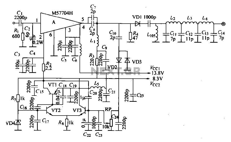
The FM radio transmitter is a high-frequency amplifier circuit that utilizes the Mitsubishi frequency set, specifically the M57704H discharge path. It operates within the frequency range of 457-458 MHz and has a transmission power of 5 watts. As illustrated...
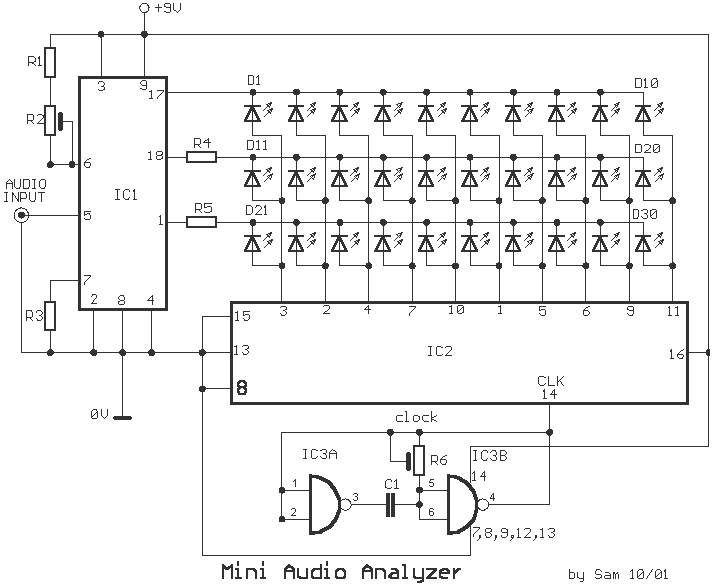
This analyst is a sensitive instrument in the frequency changes and width of an acoustic signal. Thus, the brightness of the LED that turns on each moment is proportional to the signal width, while the color is proportional to...
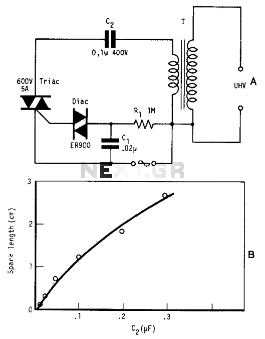
By repetitively charging and discharging a capacitor through the primary winding of an induction coil with high voltage, an ultra-high electromotive force (emf) is induced in the secondary winding. Switching is performed by a triac, which is triggered by...
The 555 timer is a highly versatile integrated circuit that can be utilized to construct a wide variety of circuits. It can be effectively used without a detailed understanding of the function of each pin. The 555 timer is commonly...
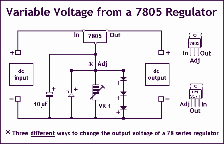
As Ron suggests, controlling the output voltage from a regulator can be made variable in three ways. Using a fixed reference zener diode to increase the output by the value of the zener. A variable resistor for variable output,...
Let's face it, not every day is the greatest. Sometimes, one may not feel like doing much of anything. Wouldn't it be nice if there was a way to change brain waves at the push of a button? Transcranial...