
RF Spectrometer
The A3008 serves as a crucial component in RF signal analysis and measurement systems. Its capability to accurately measure RF power across a specified frequency range makes it an invaluable tool for applications requiring precise RF monitoring. The integration with LWDAQ software enhances its functionality, allowing for the visualization and analysis of RF data in real-time. The design considerations, such as the implementation of the MAX2624 VCO and the low-pass filtering stage, are pivotal in ensuring signal integrity and measurement accuracy. Moreover, the calibration mechanisms incorporated in the firmware versions demonstrate a commitment to maintaining performance consistency under varying operational conditions. The distinct differences between the A3008A and A3008B versions highlight the adaptability of the design to meet diverse application requirements while maintaining a straightforward operational framework. Overall, the A3008 embodies a robust solution for RF power measurement, providing essential features for both laboratory and field applications.The A3008, when plugged into the same LWDAQ Multiplexer, can create bad messages in a Data Receiver ( A3018 ). Set the A3008 local oscillator to its minimum (DAC count 0) or maximum (DAC count 255) frequency to reduce the bad message rate.
Even better: unplug the A3008 when you`re not using it. The RF Spectrometer (A3008) measures RF powe r in 3-MHz windows between 850 MHz and 1100 MHz. If you connect the A3008`s RF input to an antenna, the A3008 will measure the power spectrum of RF signals arriving at the antenna with 1-MHz resolution and sensitivity 10 pW ( ’80 dBm). You can use the A3008 to measure average power or peak power. If you would like some help with radio-frequency jargon, see our presentation of Terminology. The A3008 is a LWDAQ device. The LWDAQ software `s RFPM Instrument (radio frequency power meter) obtains RF power measurements from the A3008 and the Spectrometer Tool gathers these power measurements together into a graph.
The A3008 allows us to measure the ambient radio frequency power in the 875 MHz to 1050 MHz range, so that we can choose a 20-MHz wide band free of interference in which to operate our Subcutaneous Transmitter ( A3009 ). We can also use the A3008 to measure the power received by an antenna from such transmitters, even though the transmitters are active for only 7 s out of every 2000 s.
The A3008, combined with the RFPM instrument, allow us to measure peak power received rather than average power, and this peak power will detect the bursts of power from our transmitters. The A3008 uses an eight-bit DAC to set the TUNE input of a MAX2624 VCO. For DAC values 0 to 255, the VCO output frequency increases from roughly 850 MHz to 1050 MHz. The A3008`s RF input is amplified and passes into a mixer, where it is downshifted by the VCO frequency.
The resulting IF is low-pass filtered with cut-off frequency 1. 5 MHz. The power present at the output of the low-pass filter is proportional to the power present at the A3008`s RF input in a 3-MHz wide frequency window centered upon the VCO frequency. All version of the A3008 suffer from a +0. 4 MHz/ °C shift in measured frequency with ambient temperature. This shift occurs as the VCO frequency changes by ’0. 4 MHz/ °C. Firmware P3008A01. abl for the A3008A suffers from calibration drift as you take continuous spectra. The VCO warms up as you use it, but cools down when you don`t. Firmware version P3008A02. abl for the A3008A solves this problem by leaving the VCO on all the time, so it reaches thermal equillibrium.
But you must let the spectrometer warm up for a few minutes to allow it to reach this equillibrium. The A3008B provides a READY light that flashes after power-up until the warm-up period has expired. The A3008 is a simple circuit. It uses no sophisticated components, other than the programmable logic chip that does the job of communicating with our data acquisition system. The A3008A and A3008B differ in several respects, as described below. The two versions have enough circuit differences that they have separate schematics. S3008A_2 : The antenna aplifier, mixer, low-pass filter, IF amplfiers, gain selector, local oscillator, local oscillator control, calibration oscillator, and calibration frequency SAW filters.
S3008B_2 : The antenna aplifier, mixer, low-pass filter, IF amplfiers, gain selector, local oscillator, local oscillator control, calibration splitter and calibration socket. The A3008 amplifies its RF input by 18 dB and feeds it into a frequency mixer for downshifting. The mixer`s LO signal comes from a MAX2624, whose output frequency is set by its TUNE input, as shown in the figure below.
The IF output from the mixer passes through a 1. 6 MHz low-pass filter. The filtered IF signal is the downshifted version of the RF frequencies within 1. 6 MHz of the LO frequency. Example: If the LO frequency is 950 MHz, then any RF signal whose frequency is in the range 950 ± 🔗 External reference
Related Circuits
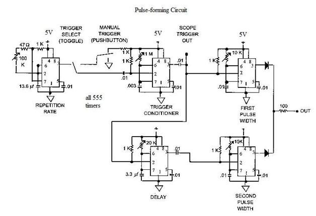
Home-built NMR spectrometer, illustrating the construction and circuitry. Demonstrates 90-degree and 180-degree pulse sequences, as well as the generation of FIDs and spin echoes at 18 MHz. The home-built NMR (Nuclear Magnetic Resonance) spectrometer is an intricate device designed for...
A spectrometer is an instrument used to view and analyze a spectrum of a specific characteristic of a substance, such as mass-to-charge values in mass spectrometry or wavelengths in absorption spectrometry, including techniques like nuclear magnetic resonance spectroscopy and...
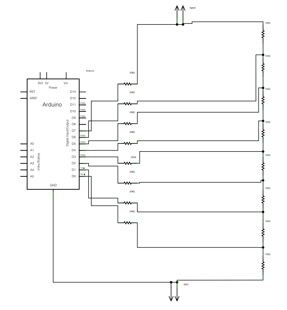
The main concept is to space the time intervals to increment the DAC output values. There are 256 levels since there are 8 digital outputs from the Arduino board. Therefore, for an 8-bit resolution and a 50-second ramp time,...