
ramped magnetic field circuit for a miniature mass spectrometer
The R-2R ladder DAC is a widely used circuit for converting digital signals into analog voltages. This circuit employs a network of resistors arranged in a specific manner to achieve the desired output. The R-2R ladder consists of two resistor values: R and 2R. Each bit of the digital input corresponds to a switch that connects either to a reference voltage (V_ref) or ground (0V).
In the context of an 8-bit DAC, there are 8 digital inputs, each controlling a switch. When a switch is connected to V_ref, it contributes to the output voltage, while connecting to ground eliminates its contribution. The output voltage is calculated based on the binary representation of the inputs, where each bit represents a different weight in the overall voltage calculation. The most significant bit (MSB) has the highest weight, while the least significant bit (LSB) has the lowest.
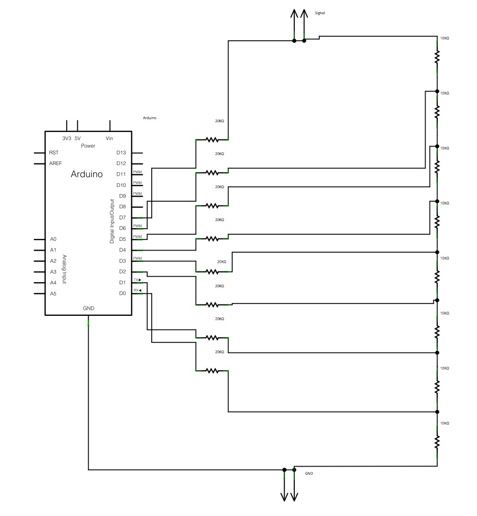
For the timing aspect, with a specified ramp time of 50 seconds, the circuit must increment the output voltage level every (50/256) seconds, allowing for a smooth transition across all 256 levels. This timing can be managed using a microcontroller, such as an Arduino, which generates the necessary control signals to toggle the switches in the R-2R ladder.
The precision of this DAC largely depends on the tolerance of the resistors used. It is essential to use high-precision resistors to ensure that the output voltage levels are accurate and consistent. Furthermore, the circuit can be enhanced by adding a low-pass filter at the output to smooth out any rapid fluctuations in voltage, resulting from the switching of the digital inputs.
In summary, the R-2R ladder DAC provides an efficient means of converting digital signals to analog voltages, with the Arduino controlling the timing and sequence of the output levels to create a smooth ramp waveform. The schematic representation created using Fritzing visually illustrates the arrangement of the resistors and the connections to the Arduino, facilitating a clear understanding of the circuit's operation.The general idea is to space the time internals to increment the DAC output values. There would be 256 levels since there are 8 digital outputs from the Arduino board. Therefore, for an 8-bit, 50s ramp time for example, the way to generate a digital ramp waveform is to increment every level per (50/256)s. No matter what the code will be, a DAC is required to convert digital signal to analog signal. An R-2R Ladder is a simple and inexpensive way to perform digital-to-analog conversion, using repetitive arrangements of precision resistor networks in a ladder-like configuration. Now I use fritzing to draw the schematic of R-2R ladder DAC circuit. 🔗 External reference
Related Circuits
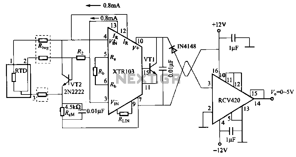
When the RTD temperature sensor is positioned far from the amplifier, the resistance of the sensor leads and their susceptibility to interference and other issues cannot be overlooked. The circuit shown in the figure addresses this problem. It utilizes...
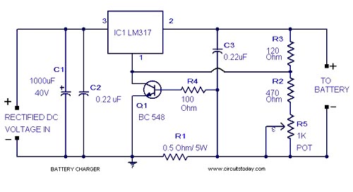
A simple lead-acid battery charger circuit with a diagram and schematic using the IC LM317, which provides the correct battery charging voltage. This lead-acid battery charger should be supplied with an input of 18 volts to the IC. The lead-acid...
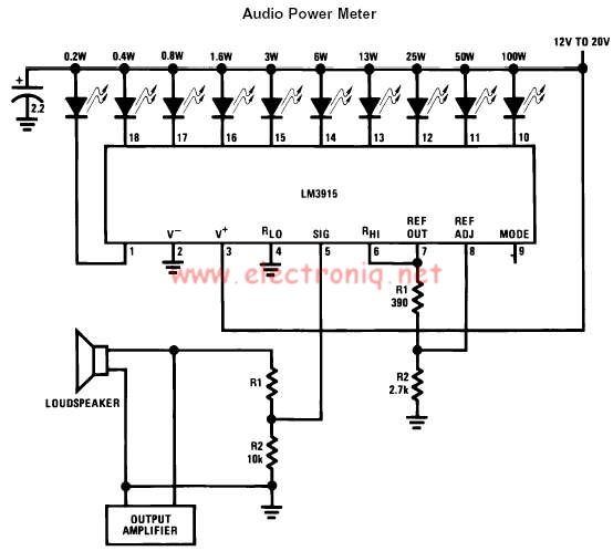
The LM3915 monolithic integrated circuit can be used to design a simple audio power level meter that senses analog voltage levels and drives ten LEDs, LCDs, or vacuum fluorescent displays, providing a logarithmic 3 dB/step analog display. One pin...
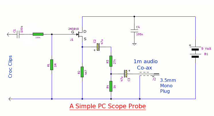
This simple PC scope probe functions as a FET follower, featuring high input impedance and low output impedance to match a microphone or line input socket on a PC or laptop. This design allows for practical examination of waveforms...
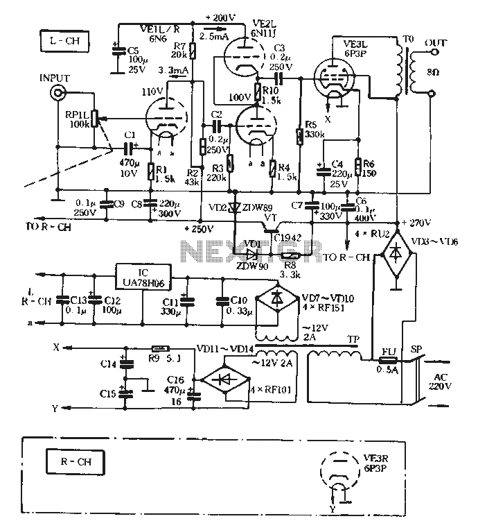
The VE1 preamplifier utilizes a low muscle, low resistance double triode 6N6 configuration, with separate halves for the left and right audio channels. The design operates within the CPI framework. It promotes the use of high-level VE2 household low...
This charger is based on a charging voltage of 2.4 volts per cell, in accordance with most manufacturers' recommendations. This circuit pulses the battery with 14.4 volts (6 cells x 2.4 volts per cell) at a rate of 120...
Warning: include(partials/cookie-banner.php): Failed to open stream: Permission denied in /var/www/html/nextgr/view-circuit.php on line 713
Warning: include(): Failed opening 'partials/cookie-banner.php' for inclusion (include_path='.:/usr/share/php') in /var/www/html/nextgr/view-circuit.php on line 713