
RF VOLTMETER
The described circuit employs a photochopper modulator as a key component for detecting RF voltage levels. By converting the RF signal into a low-frequency waveform, the circuit enables precise measurements of low-level RF voltages. The use of a photochopper allows for effective isolation and modulation of the RF signal, which enhances the accuracy of the error detection process.
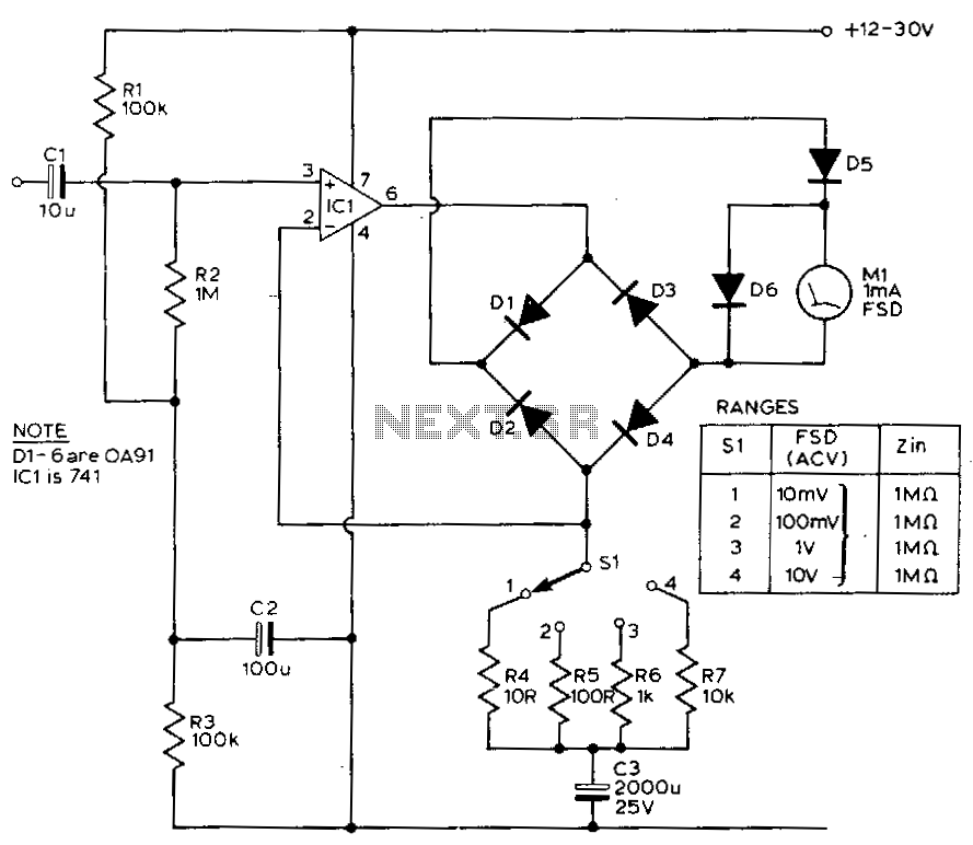
The circuit operates within specified voltage ranges, providing flexibility for various applications. The seven selectable voltage ranges allow for measurements from 10 mV RMS, suitable for detecting weak signals, to 10 V RMS, accommodating stronger RF voltages. This adaptability is crucial for applications that require precise measurement across a wide dynamic range.
The frequency response of the circuit is noteworthy, extending from 500 kHz to 1,000 MHz. This broad frequency range ensures that the circuit can effectively measure RF signals across a variety of communication and broadcasting applications, making it suitable for both laboratory and field use.
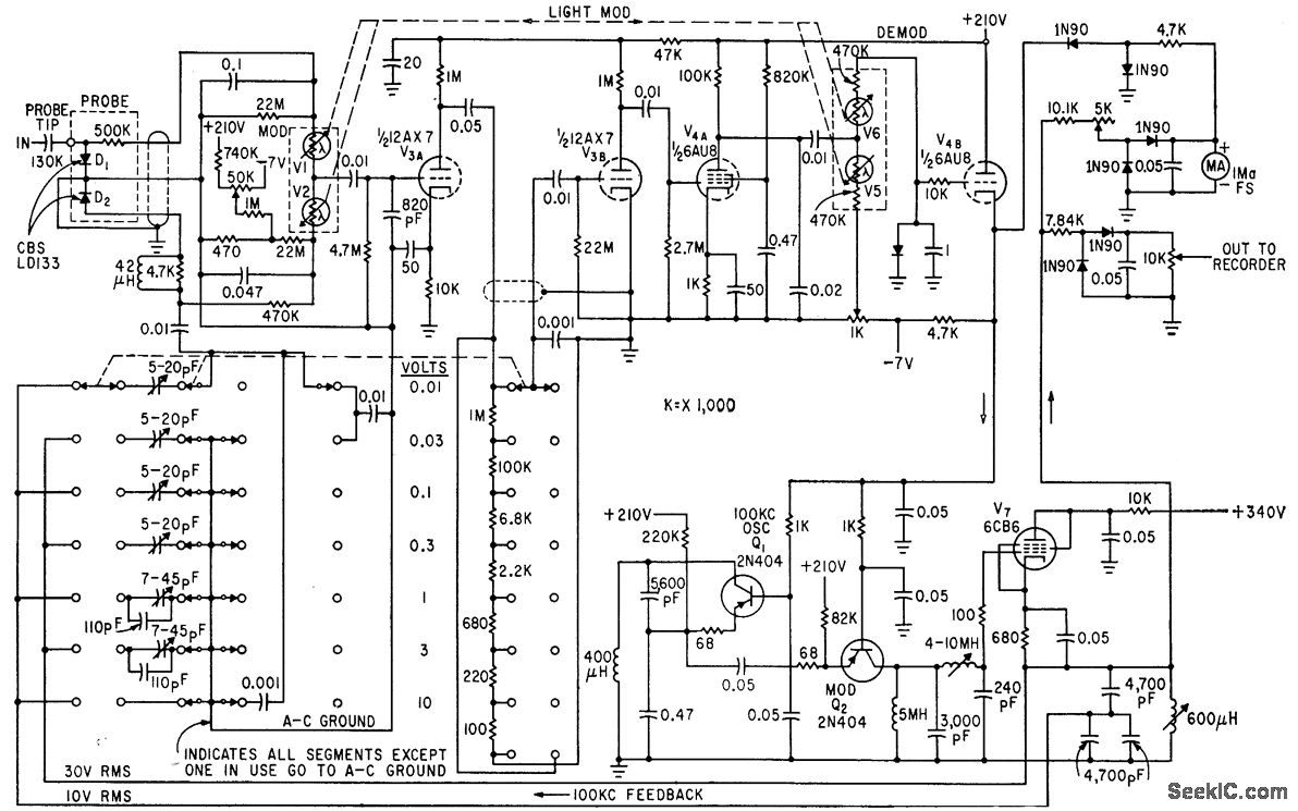
Overall, the combination of a photochopper modulator for error detection, along with the wide voltage and frequency ranges, results in a robust and versatile circuit for measuring low-level RF voltages. This design is particularly beneficial in electronics and telecommunications, where accurate measurement of RF signals is essential for system performance and reliability.Circuit generates low-frequency waveform whose amplitude is equivalent to that of unknown r-f voltage, using photochopper modulator VI-V2 as error detector. Arrangement gives seven voltage ranger from 10 my rms to 10 v rms full scale, over frequency range of 500 kc to 1, 000 Mc.
-T. C. Anderson, Measuring Low-Level R-F Voltage with Servo Feedback Te chniques, Electronics, 34:28, p 63-65. 🔗 External reference
Related Circuits
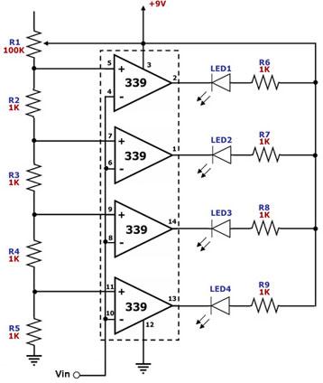
This circuit is designed as a simple LED bar graph voltmeter. Each operational amplifier in the LM339 quad package functions as a comparator, comparing the input voltage (Vin) to a series of fixed voltage levels that are proportional to...
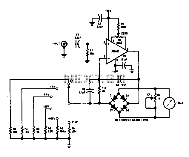
This voltmeter is capable of measuring AC signals as low as 15 mV at frequencies from 100 Hz to 500 kHz. Full-scale sensitivity may be changed by altering the values of R1 through R6 (R = Vin/100 µA). The described...
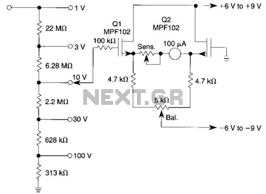
This voltmeter utilizes a pair of JFETs in a balanced-bridge source-follower amplifier circuit. Q1 and Q2 should be matched within 10% for IDSS. This configuration minimizes meter drift and maintains bridge balance over temperature. The described voltmeter is an advanced...
This circuit exhibits a flat frequency response from 8 Hz to 50 kHz, maintaining a -3 dB level at the 10 mV range. Furthermore, while the upper frequency limit remains consistent across less sensitive ranges, the lower frequency limit...
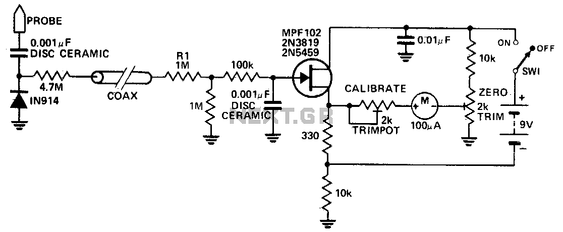
This circuit measures RF voltages exceeding 200 MHz and reaching up to approximately 5 V. The diode must be installed in a remote probe, positioned near the probe tip. The sensitivity is exceptional, allowing for the measurement of voltages...
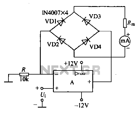
An operational amplifier, a diode bridge rectifier, and DC mA AC voltmeter tables are illustrated in the figure. The operational amplifier used is the LM324. The measured AC voltage is applied to the inverting terminal of the operational amplifier,...