
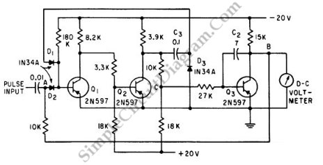
Sensitive rf voltmeter
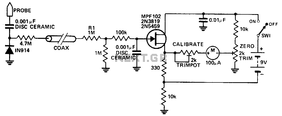
The RF voltage measurement circuit is designed to operate efficiently in high-frequency applications, specifically in the range beyond 200 MHz. The core component of this circuit is a diode, which is strategically placed in a remote probe. This configuration enhances the accuracy and responsiveness of the circuit, as the diode's proximity to the probe tip allows for minimal signal loss and distortion during measurement.
The circuit is capable of detecting very low voltage levels, with a sensitivity threshold that permits the measurement of RF voltages as low as 1 V peak. This makes it particularly useful in environments where signal strength may be weak, such as in certain RF communication applications or in the testing of RF components.
Calibration of the unit is straightforward, involving the connection of the probe input to a known RF voltage source, typically a calibrated signal generator. This allows for precise adjustments to be made using the calibration control, ensuring that the readings from the circuit are accurate and reliable. Proper calibration is essential for maintaining the integrity of measurements, especially in critical applications where precise voltage levels are necessary for effective performance.
Overall, this circuit design provides a robust solution for measuring high-frequency RF voltages, combining sensitivity, ease of calibration, and effective placement of components to achieve high performance in a variety of electronic testing scenarios.This circuit measures RF voltages beyond 200 MHz and up to about 5 V. The diode should be mounted in a remote probe, close to the probe tip. Sensitivity is excellent and voltages less than 1 V peak can be easily measured The unit can be calibrated by connecting the input to a known level of RF voltage, such as a calibrated signal generator, and setting the calibrate control. 🔗 External reference
Related Circuits
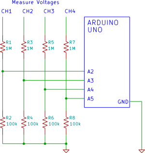
A four-channel voltmeter that displays voltage readings in a software application running on a computer. An Arduino reads the voltages and sends them to an application written in the Processing language. The described circuit comprises a four-channel voltmeter system that...
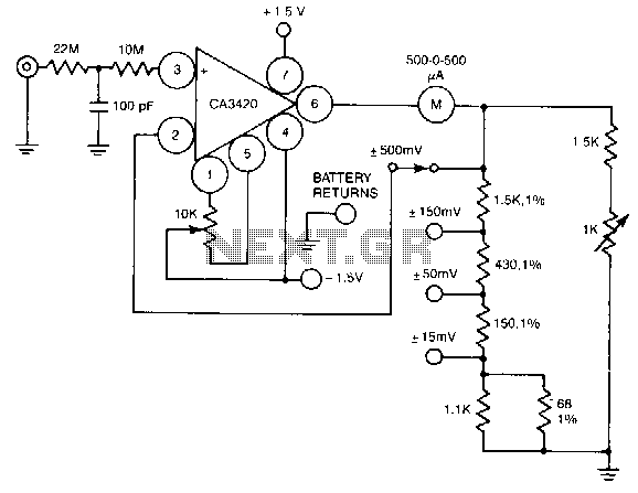
A resistance of 1,000,000 MΩ takes advantage of the high input impedance of the CA3420 BiMOS op-amp. Only two 1.5-V AA-type penlite batteries are required for use. Full-scale deflection is ±500 nV, ±150 mV, and ±15 mV. The circuit utilizes...
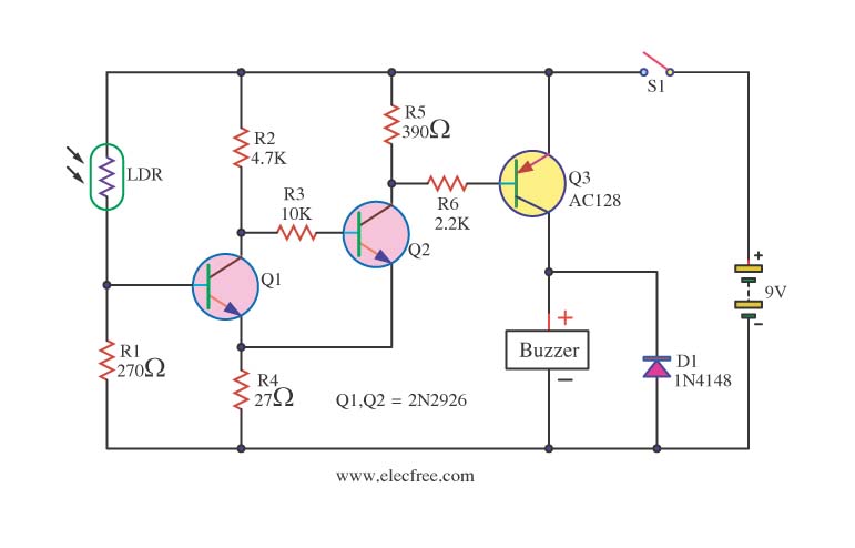
This circuit activates a warning when it becomes dark, functioning as a light-sensitive switch. The essential electronic components include the 2N2926 and AC128 transistors. The described light-sensitive switch circuit is designed to detect ambient light levels and activate an output...
This is a Peak Voltmeter circuit. This circuit can be viewed as a pulse stretcher, which captures fast pulse signals to be measured by a slow response voltmeter. The Peak Voltmeter circuit is designed to accurately measure the peak voltage...
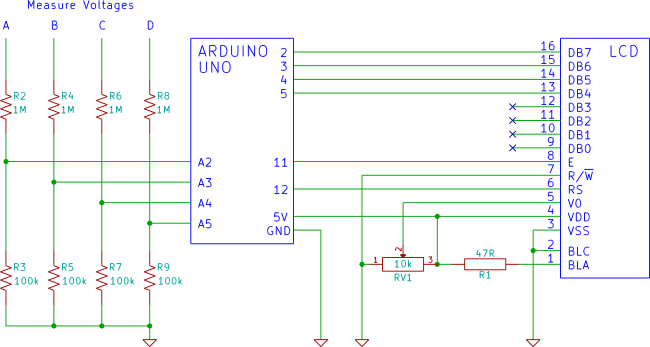
An Arduino voltmeter that displays voltage on an LCD display. The voltmeter has 4 channels for measuring four different voltages. The Arduino voltmeter utilizes an Arduino microcontroller to measure and display voltage levels on a Liquid Crystal Display (LCD). This...

This FETVM replaces the function of the VTVM while eliminating the need for a traditional line cord. Additionally, it offers significantly improved drift rates compared to vacuum tube circuits, enabling a 0-volt full-scale range that is generally impractical with...