
Ring-detector

This circuit detects the 20 Hz, 86-V rms ring signal on telephone lines and initiates action in an electrically isolated circuit. Typical applications include automatic answering equipment, interconnect/interface systems, and key systems. The illustrated circuits are basic designs intended to demonstrate concepts. They may not fully address AC/DC ring differentiation, 60-Hz noise rejection, dial tap rejection, and other effects that must be considered in field applications. The first ring detector is the simplest, providing about 1 mA of signal for a 7 mA line loading for 1/10 second after the start of the ring signal. The time delay capacitor offers a degree of dial tap and click suppression, as well as filtering out the zero crossing of the 20-Hz wave. This circuit serves as a basis for a simple example, a ring extender that operates lamps and buzzers from the 120-V, 60-Hz power line while maintaining positive isolation between the telephone line and the power line. The use of the isolated tab triac simplifies heat sinking by removing the need to isolate the triac heatsink from the chassis. Lower line current loading is required in many ring detector applications, which can be achieved using the HllBX522 photo-Darlington optocoupler, specified to provide a 1 mA output from a 0.5 mA input across the -25°C to +50°C temperature range. The next circuit allows ring detection down to a 40-V rms ring signal while providing 60-Hz rejection down to about 20-V rms. Zero-crossing filtering can be implemented either at the input bridge rectifier or at the output. Reliable ring detection requires the circuit to respond only to ring signals while rejecting spurious noise of similar amplitude, such as dialing transients. The configuration relies on the fact that ring signals consist of continuous frequency bursts, whereas dialing transients have a much lower repetition rate. The de bridge-filter combination at the HllL input has a time constant that prevents it from reacting to widely spaced dialing transients but allows it to detect the presence of relatively long-duration bursts, causing the HllL to activate the downstream interconnect circuits at a precisely defined threshold.
The described circuit serves as a fundamental solution for detecting ring signals in telecommunication applications. It operates by identifying the specific frequency and amplitude characteristics of the ring signal while ensuring electrical isolation from the power line, which is critical for safety and functionality. The initial design utilizes a simple ring detector that generates a signal sufficient to trigger downstream devices, such as lamps and buzzers, indicating an incoming call. The inclusion of a time delay capacitor is essential for mitigating false triggers caused by transient signals, enhancing the reliability of the detection.
The use of an isolated tab triac for switching provides a significant advantage in thermal management, as it facilitates the integration of the triac into the system without the need for complex heat sinking solutions. This is particularly beneficial in compact designs where space is limited. Furthermore, the HllBX522 photo-Darlington optocoupler is an effective component for applications requiring low current operation, allowing for efficient signal processing without overloading the line.
The second circuit variant expands the detection capability to lower voltage ring signals, enhancing versatility in various applications. The design incorporates zero-crossing filtering techniques, which can be strategically placed at either the input or output, ensuring that only valid ring signals are processed. This filtering is crucial for maintaining performance in environments with significant electrical noise, as it allows the circuit to differentiate between legitimate ring signals and unwanted transients.
In essence, the circuit's design principles focus on reliable detection, noise rejection, and isolation, making it suitable for a range of telecommunication devices. The careful consideration of component selection and circuit topology ensures that the system operates efficiently across a specified range of conditions, thereby fulfilling the requirements for modern telecommunication applications.This circuit detects the 20 Hz, "" 86-V rms ring signal on telephone lines and initiates action in an electrically isolated circuit. Typical applications would include automatic answering equipment, and interconnect/ interface and key systems.
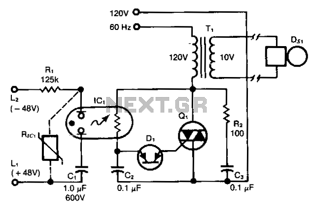
The circuits illustrated are bare bones circuits designed to illustrate concepts. They might not eliminate the ac/dc ring differentiation, 60-Hz noise rejection, dial tap rejection, and other effects that must be considered in field application. The first ring detector is the simplest and provides about 1-mA signal for a 7-mA line loading for 1/10 sec after the start of the ring signal. The time delay capacitor provides a degree of dial tap and click suppression, as well as filtering out the zero crossing of the 20-Hz wave.
This circuit provides the basis for a simple example, a ring extender that operates lamps and buzzers from the 120-V, 60-Hz power line, while maintaining positive isolation between the telephone line and the power line. Use of the isolated tab triac simplifies heat sinking by removing the constraint of isolating the triac heatsink from the chassis.
Lower line current loading is required in many ring detector applications. This can be provided by using the HllBX522 photo-Darlington optocoupler, which is specified to provide a 1-mA output from a 0.5-mA input through the -25°C to +50°C temperature range. The next circuit allows ring detection down to a 40-V rms ring signal while providing 60-Hz rejection to about 20-V rms.
Zero-crossing filtering can be accomplished either at the input bridge rectifier or at the output. Dependable ring detection demands that the circuit responds only to ring signals, rejecting spurious noise of similar amplitude, such as dialing transients. The configuration shown relies on the fact that ring signals are composed of continuous frequency bursts, whereas dialing transients are much lower in repetition rate.
The de bridge-filter combination at the HllL input has a time constant; it cannot react to widely spaced dialing transients, but will detect the presence of relatively long duration bursts, causing the HllL to activate the downstream interconnect circuits at a precisely defined threshold.
The described circuit serves as a fundamental solution for detecting ring signals in telecommunication applications. It operates by identifying the specific frequency and amplitude characteristics of the ring signal while ensuring electrical isolation from the power line, which is critical for safety and functionality. The initial design utilizes a simple ring detector that generates a signal sufficient to trigger downstream devices, such as lamps and buzzers, indicating an incoming call. The inclusion of a time delay capacitor is essential for mitigating false triggers caused by transient signals, enhancing the reliability of the detection.
The use of an isolated tab triac for switching provides a significant advantage in thermal management, as it facilitates the integration of the triac into the system without the need for complex heat sinking solutions. This is particularly beneficial in compact designs where space is limited. Furthermore, the HllBX522 photo-Darlington optocoupler is an effective component for applications requiring low current operation, allowing for efficient signal processing without overloading the line.
The second circuit variant expands the detection capability to lower voltage ring signals, enhancing versatility in various applications. The design incorporates zero-crossing filtering techniques, which can be strategically placed at either the input or output, ensuring that only valid ring signals are processed. This filtering is crucial for maintaining performance in environments with significant electrical noise, as it allows the circuit to differentiate between legitimate ring signals and unwanted transients.
In essence, the circuit's design principles focus on reliable detection, noise rejection, and isolation, making it suitable for a range of telecommunication devices. The careful consideration of component selection and circuit topology ensures that the system operates efficiently across a specified range of conditions, thereby fulfilling the requirements for modern telecommunication applications.This circuit detects the 20 Hz, "" 86-V rms ring signal on telephone lines and initiates action in an electrically isolated circuit. Typical applications would include automatic answering equipment, and interconnect/ interface and key systems.
The circuits illustrated are bare bones circuits designed to illustrate concepts. They might not eliminate the ac/dc ring differentiation, 60-Hz noise rejection, dial tap rejection, and other effects that must be considered in field application. The first ring detector is the simplest and provides about 1-mA signal for a 7-mA line loading for 1/10 sec after the start of the ring signal. The time delay capacitor provides a degree of dial tap and click suppression, as well as filtering out the zero crossing of the 20-Hz wave.
This circuit provides the basis for a simple example, a ring extender that operates lamps and buzzers from the 120-V, 60-Hz power line, while maintaining positive isolation between the telephone line and the power line. Use of the isolated tab triac simplifies heat sinking by removing the constraint of isolating the triac heatsink from the chassis.
Lower line current loading is required in many ring detector applications. This can be provided by using the HllBX522 photo-Darlington optocoupler, which is specified to provide a 1-mA output from a 0.5-mA input through the -25°C to +50°C temperature range. The next circuit allows ring detection down to a 40-V rms ring signal while providing 60-Hz rejection to about 20-V rms.
Zero-crossing filtering can be accomplished either at the input bridge rectifier or at the output. Dependable ring detection demands that the circuit responds only to ring signals, rejecting spurious noise of similar amplitude, such as dialing transients. The configuration shown relies on the fact that ring signals are composed of continuous frequency bursts, whereas dialing transients are much lower in repetition rate.
The de bridge-filter combination at the HllL input has a time constant; it cannot react to widely spaced dialing transients, but will detect the presence of relatively long duration bursts, causing the HllL to activate the downstream interconnect circuits at a precisely defined threshold.
Related Circuits
This ring detector, utilizing a neon-LDR (light-dependent resistor) optocoupler, simplifies interfacing with telephone lines. The ring detector circuit is designed to detect the ringing signal from telephone lines, which typically operates at a frequency of 20 Hz to 25 Hz...