
Robot Tutorials current sensor
The operation of these devices is straightforward: applying voltage to the component allows for a quick readout of the current being drawn. However, there are notable disadvantages. The accuracy of these devices is limited, often measuring in increments rounded to the nearest 10mA, which may be sufficient for high-power applications but problematic for low-current devices. Timing is another concern, as benchtop power supplies usually take measurements at fixed intervals, generally three times per second. This can lead to inaccuracies in readings for devices that exhibit rapid current fluctuations. Furthermore, many current sensing devices lack data logging capabilities, hindering complex current draw analysis on a computer.
Digital multimeters are another commonly used tool for measuring various circuit characteristics, including voltage, current, capacitance, resistance, temperature, and frequency. They are essential for robotics projects, with prices ranging from approximately $10 to $100, depending on features and accuracy. To measure current with a digital multimeter, the leads must be connected in series with one of the power source wires. Similar to benchtop power supplies, digital multimeters also face timing issues, but they generally offer slightly better accuracy. Some multimeters come equipped with computer linkup cables for data logging, allowing for the collection and analysis of current data.
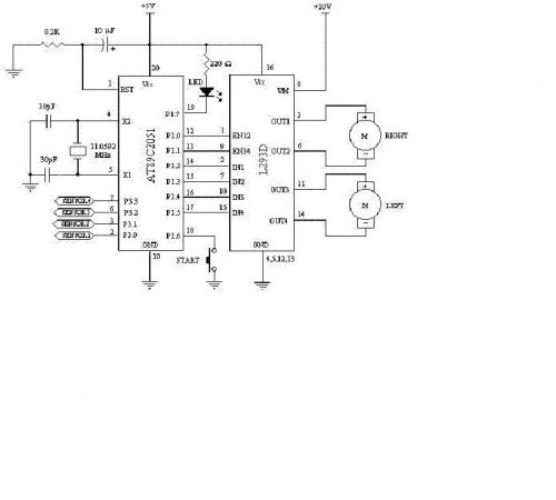
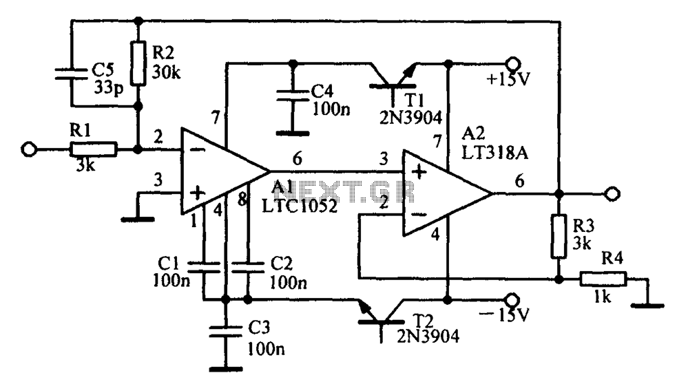
A particular chip, costing around $5, utilizes a tiny resistor and a built-in high-gain amplifier to output a voltage proportional to the current flowing through it. This chip can be placed in series with the component being measured, with its output connected to a data logging device such as a microcontroller. The microcontroller can transmit data to a terminal on a computer, facilitating further analysis using software like Excel. The accompanying schematic can measure the current usage of a servo, but it is versatile enough to measure current from other devices without modification, and it can even handle multiple items simultaneously. An optional capacitor can be included in the circuit to serve as a voltage buffer, ensuring maximum continuous current delivery.Current sensing is as it says - sensing the amount of current in use by a particular circuit or device. If you want to know the amount of power being used for any robot component, current sensing is the way to go.
Current sensing is not a typical application in robotics. Most robots would never need a current sensing ability. Current sensing is a way for a robot to measure it`s internal state and rarely required to explore the outside world. It is useful for a robot builder to better understand power use of the various components within a robot. Sensing can be done for DC motors, circuits, or servos to measure actuator power requirements. It can be done for things like microcontrollers to measure power performance in different situations.
It can be useful for things like robot battery monitors. And lastly, robot hand grasp detection devices and collision detection. For example, if the current use suddenly increases, that means a physical object is causing resistance. This device is somewhat expensive as it ranges in the hundreds, but they are very common and you can easily find one available in any typical university lab.
These devices are a must for any electrical engineer or robot builder. Operation of this device should be straigtforward. Apply a voltage to your component, and it will quickly give a readout of the current you are drawing. Although this takes seconds and little effort to do, there are a few disadvantages to this method. The first disadvantage is that it is not highly accurate. Usually they can only measure in increments rounded off to the nearest 10mA. This is fine for high powered applications where an extra 5mA does not matter, but for low current draw devices this can be an issue.
The next disadvantage is timing. A benchtop power supplies only takes current measurements in set periods of time - usually 3 times a second. If your device draws a steady current over time this is not a problem. But if for example your device ramps from 0 to 3 amps five times a second, the current reading you get will not be accurate.
The last major disadvantage is that there is no data logging ability - therefore you cannot analyze any complex current draw data on a computer. The digital multimeter is another commonly available device capable of analyzing many different characteristics of your circuit - voltage, current, capacitance, resistance, temperature, frequency, etc.
If you do not already have one, you definitely need one to make a robot. It would be like cooking without heat if you didnt have one. . . For cost, they range in price from around $10 to about $100. The price depends on features and accuracy. To measure current, all you do is connect your two leads in series with one of your power source wires. But again, there are disadvantages to this method. Like the benchtop power supplies, digital multimeters suffer timing issues. However, accuracy is usually an extra one or two decimal places better. Good enough for most applications. As for data logging, several available multimeters actually have computer linkup cables so that you may record current data to process later.
This ~$5 chip, using a really tiny resistor and a built in high gain amplifier, outputs a voltage in proportion to the current passing through it. Put the chip in series with what you want to measure, and connect the output to a data logging device such as a microcontroller.
The microcontroller can print out data to hyperterminal on your computer, and from there you can transfer it to any data analyzing program you wish (like Excel). This particular schematic below (click for the full expanded circuit) can measure current use of a servo.
But it can easily measure current from any other device with no modification - and even multiple items simultaneously too! The capacitor is optional as it acts as a voltage buffer, ensuring maximum continuous current. 🔗 External reference
Related Circuits
Constructing a robot, or rather a vehicle, that uses two motors. Reference materials regarding the schematics for the circuit design have been obtained, but the current schematics utilize smaller motors that draw less power and operate with a lower...
The wire connected to the 5V pin is linked to the positive pins of the breadboard, which are not connected to any other components. There are no additional connections on the positive column. While this may seem like a...
This current-limiting circuit, illustrated in this example as part of a small bench power supply, could theoretically be utilized alongside any dual-rail current source. The section of the circuit to the left of the diagram restricts the input current...
Parts List The circuit was specifically designed for shop window animation as it utilizes a capacitive sensor that is activated by a touch control system. The circuit is intended for enhancing visual displays in retail environments by creating dynamic animations...
The following circuit illustrates an LM555 integrated circuit (IC) motion detector utilizing infrared sensors. Features include the generation of an infrared pulse modulation at 5 kHz, along with bandwidth control. The LM555 timer IC is a versatile component widely used...
Amplifying circuit diagram to enhance the output current and voltage. An amplifying circuit is designed to increase the amplitude of an input signal, resulting in a higher output current and voltage. This type of circuit is commonly utilized in various...