
A circuit diagram of an amplifier circuit to enhance the output current and voltage
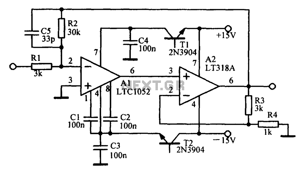
An amplifying circuit is designed to increase the amplitude of an input signal, resulting in a higher output current and voltage. This type of circuit is commonly utilized in various electronic applications, such as audio systems, instrumentation, and communication devices.
The basic components of an amplifying circuit typically include transistors (BJT or FET), resistors, capacitors, and sometimes operational amplifiers (op-amps). The configuration of these components can vary based on the desired amplification characteristics, such as gain, bandwidth, and input/output impedance.
In a common transistor amplifier configuration, the transistor operates in its active region, where it can effectively amplify the input signal. The input signal is applied to the base (or gate) of the transistor, while the output is taken from the collector (or drain). Resistors are used to set the biasing conditions of the transistor, ensuring it remains in the active region during operation. Coupling capacitors may be employed to block DC components while allowing AC signals to pass through, thereby isolating different stages of amplification.
For further enhancement of performance, feedback mechanisms can be introduced. Negative feedback can stabilize the gain and improve linearity, while positive feedback can be used in specific applications to increase gain further. The choice of components and configuration will ultimately depend on the specific requirements of the application, including the desired frequency response and power handling capabilities.
In summary, an amplifying circuit is crucial for boosting signal strength in various electronic applications, and careful design considerations are necessary to achieve optimal performance.Amplifying circuit diagram to enhance the output current and voltage:
Related Circuits
This circuit features a micro vibration sensor, a trigger delay circuit, and a control circuit, as illustrated in the accompanying figure. The micro vibration sensor comprises a vibration sensing device and a high power amplifier circuit, enabling it to...
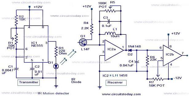
Infrared (IR) Motion Detector Circuit featuring a motion detector alarm and an infrared sensor. The circuit diagram and its operation are provided in detail. The infrared (IR) motion detector circuit is designed to detect motion within a specified range and...
This circuit utilizes the MM74HC942, a single-chip low-speed modem that is compatible with the Bell 103 standard. The Bell 103 modem circuit operates at a baud rate of 300. The MM74HC942 is a versatile integrated circuit designed for low-speed data...

To utilize this facility, the calling subscriber must first dial the standard phone number of the intended recipient. Once the call is connected, the calling party does not hear a ring-back tone. The calling subscriber must then press the...
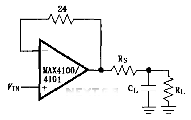
The MAX4100/4101 operational amplifiers utilize a capacitive load drive circuit with an isolation resistor Rs. The MAX4100 and MAX4101 can handle maximum capacitive loads of 5pF and 20pF, respectively, but are susceptible to overshoot and ringing oscillations. To mitigate...
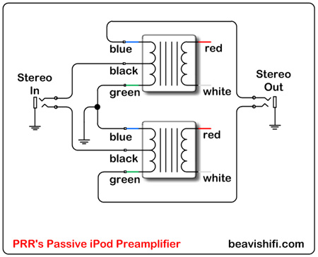
Construct a basic passive preamplifier for use with an iPod, Zune, or other portable media players. This device is particularly useful for enhancing audio quality in a car environment. A passive preamplifier is a circuit designed to amplify audio signals...