
RS232 power supply circuit diagram electronic project design
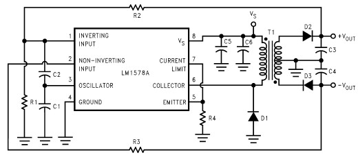
The RS232 power supply circuit is designed to efficiently convert a low input voltage into a dual output voltage of ±12V, suitable for RS-232 line drivers. The LM1578A switching regulator serves as the core component, facilitating the conversion and regulation of voltage. The circuit demonstrates an efficiency exceeding 70%, which is critical for minimizing power loss and heat generation, especially in compact applications.
Load regulation is maintained at ±1.25% across a load range of 10% to 100%, indicating that the output voltage remains stable under varying load conditions. Line regulation further ensures that fluctuations in input voltage do not significantly impact the output, with a specification of ±0.08%. The cycle-by-cycle current limit feature enhances the circuit's reliability by preventing excessive current that could damage components.
The transformer, Pulse Engineering PE-64287, features a turns ratio of 1:1.6:1.6, which is essential for stepping up the voltage to the desired levels. The primary inductance of 50 is critical for ensuring proper operation and efficiency of the transformer in the switching regulator circuit.
The list of components includes resistors R1 (10 kΩ), R2 (240 kΩ), and R3 (240 kΩ), which are used for setting the feedback and control parameters of the regulator. R4 (0.1Ω) serves as a current sensing resistor. Capacitors C1 (1000 pF) and C2 (18 pF) are used for filtering and stability, while C3 (220 µF), C4 (220 µF), and C5 (100 µF) provide bulk energy storage to smooth out the output voltage. C6 (0.1 µF) is included for high-frequency decoupling. The diodes, specifically the 1N5819 type, are used for rectification and provide a robust path for current flow while preventing reverse polarity.
Overall, this RS232 power supply circuit is an effective solution for applications requiring reliable ±12V power for RS-232 line drivers, with careful consideration given to efficiency, regulation, and component selection.This RS232 power supply circuit diagram is an simple RS-232 Line Driver Power Supply, that operates from an input voltage as low as 4. 2V, and delivers an output of ±12V at ±40 mA with an efficiency of better than 70%. This RS232 power supply circuit provides a load regulation of ±1. 25% (from 10% to 100% of full load) and a line regulation of ± 0. 08%. Other notable features include a cycle-by-cycle current limit and an output voltage ripple of less than 40 mVp-p. This power supply circuit is based on the LM1578A switching regulator designed by National Semiconductor and can be used to convert the already existing supply into a separate ±12V supply for powering the interface line drivers.
The transformer used in the power supply was a Pulse Engineering PE-64287 with turns ratio of Np:Ns:Ns = 1:1. 6:1. 6 and primary inductance of 50. Values for components are : R1 = 10 k ©, R2 = 240 k ©, R3 = 240 k ©, R4 = 0. 1 ©, C1 = 1000 pF, C2 = 18 pF, C3 = 220 F, C4 = 220 F, C5 = 100 F, C6 = 0. 1 F and all diodes are 1N5819 type. 🔗 External reference
Related Circuits
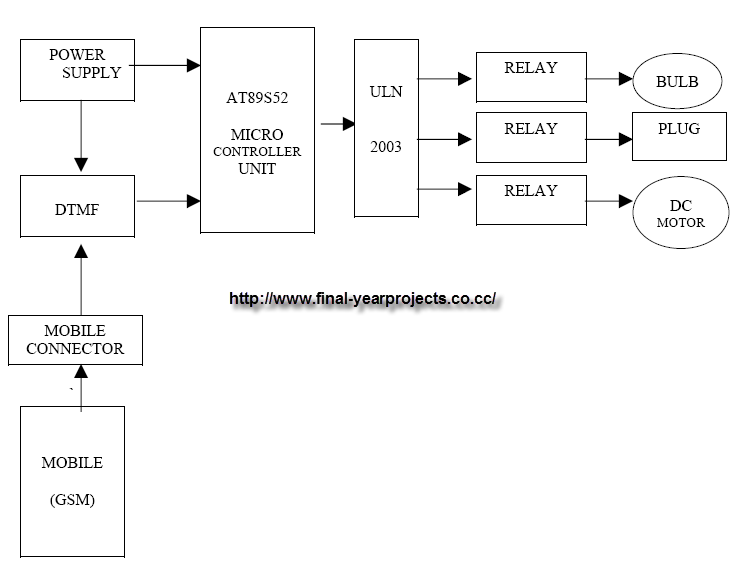
This project focuses on GSM-Based Home Automation and has been submitted as part of the requirements for a Bachelor of Technology degree in Electronics and Communication Engineering. The objective of the project is to create a system that utilizes...
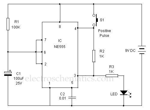
This 555 timer is designed uniquely to provide a positive output through control over its reset pin. Typically, the 555 timer IC is triggered by applying a negative voltage. The 555 timer is a versatile integrated circuit widely used in...
This design outlines a simple 1 kHz square wave generator utilizing a few components and the LM3909 integrated circuit, which is beneficial for testing audio equipment. The circuit operates on a single 1.5V battery cell, producing a maximum output...
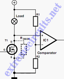
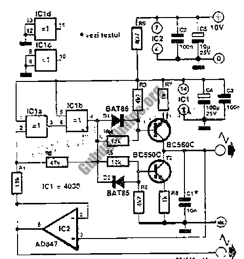
In applications where a MOSFET is used to switch a load, it is relatively straightforward to incorporate short-circuit or overload protection. This can be achieved by utilizing the internal resistance RDS(ON), which generates a voltage drop proportional to the...
This simple water detector circuit utilizes alternating voltage to prevent electrode corrosion. It is easy to construct and employs N1 as a trigger Schmitt gate to generate the AC signal. When a conductive substance, such as an aqueous solution,...
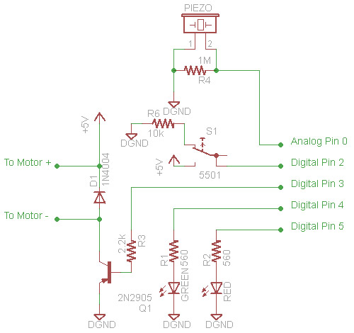
A prototype for a secret knock device was developed. This device is designed to detect a specific knock pattern that has been programmed into its system. Upon recognizing the correct knock, it activates a motor that can be utilized...
Warning: include(partials/cookie-banner.php): Failed to open stream: Permission denied in /var/www/html/nextgr/view-circuit.php on line 713
Warning: include(): Failed opening 'partials/cookie-banner.php' for inclusion (include_path='.:/usr/share/php') in /var/www/html/nextgr/view-circuit.php on line 713