
Simple water detector circuits
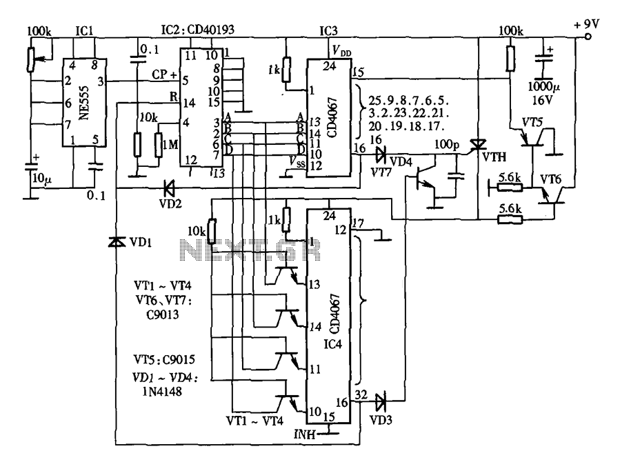
The water detector circuit is designed to monitor the presence of water or other conductive liquids. The use of alternating voltage is crucial as it minimizes the risk of corrosion on the electrodes, enhancing the longevity and reliability of the sensor. The Schmitt trigger (N1) serves as a signal conditioning component, generating a stable AC signal that is essential for the operation of the circuit.
When moisture is detected between the electrodes, the conductive path allows current to flow, which is rectified by diodes D1 and D2. This rectification process converts the AC signal into a DC voltage, which is then used to charge capacitor C4. The charge on C4 can be monitored to determine the presence of water. If the voltage across C4 exceeds a certain threshold, it can trigger additional circuitry, such as an alarm or a relay, to indicate water presence.
The design of the circuit should also include appropriate values for the resistors and capacitors to ensure sensitivity and stability. The choice of diodes is important; they should have a low forward voltage drop to ensure efficient rectification. Additionally, the layout of the circuit should minimize noise and interference, which can affect the performance of the water detection system.
Overall, this water detector circuit serves as an effective solution for applications requiring moisture detection, such as leak detection systems, agricultural monitoring, and various industrial processes. The simplicity of the design allows for easy implementation and customization based on specific requirements.This simple water detector circuit uses alternative voltage in order to prevent the corrosion of the electrodes. It is easy to build and uses N1 as a trigger Schmitt gate which generate the AC. If between the electrodes is a electricity conductor, for example an aqueous solution, then because of the rectification action of D1 and D2, the C4 capacitor is char..
🔗 External reference
Related Circuits
An advantage of a photogate over a sound trigger is that the former activates based on the exact position of the object that interrupts the beam. For instance, the shape of a snapped elastic cord can be captured as...
Below is the schematic diagram of an audio input module. This module is capable of producing a DC output voltage that is proportional to the amplitude of the input signal. The audio input module typically consists of several key components...
Most cases of infrared remote control failure can be identified by the absence of the pulsed transmitted infrared light. It is very rare that the... Infrared remote controls operate by transmitting modulated infrared light signals that are detected by a...
The lantern control circuit allows for the management of 30 outputs through an external driver circuit, specifically designed for water sports or large decorative lantern applications. The circuit features a control pulse generator, which regulates the lights, and an...
This simple water detector circuit utilizes alternating voltage to prevent the corrosion of the electrodes. It is straightforward to construct and employs N1 as a trigger Schmitt gate that generates the AC signal. When an electrical conductor, such as...

In this indicating comparator circuit, R2 sets the hysteresis. If the 741 saturates at ±12 V, the current in R1 will be approximately ±10 mA if a 0.1 V hysteresis is desired. More: Then 0.1 V/10 mA ~ 100. The...
Warning: include(partials/cookie-banner.php): Failed to open stream: Permission denied in /var/www/html/nextgr/view-circuit.php on line 713
Warning: include(): Failed opening 'partials/cookie-banner.php' for inclusion (include_path='.:/usr/share/php') in /var/www/html/nextgr/view-circuit.php on line 713