
RS232 to USB Converter
The RS232 to USB converter is an essential interface device that allows communication between devices with RS232 serial ports and modern computers that utilize USB ports. This converter is particularly useful in scenarios where older serial devices need to be integrated into contemporary computing environments, enabling data transfer and device control.
The circuit typically comprises several key components: a USB connector, an RS232 connector, and a level-shifting integrated circuit (IC) that facilitates the conversion between the two signal types. The USB connector interfaces with the host computer, while the RS232 connector connects to the serial device. The level-shifting IC, such as the MAX232 or similar, converts the voltage levels of the RS232 signals (which can range from -12V to +12V) to the 0V to +5V levels that USB devices require.
In operation, the RS232 signals are received by the level-shifting IC, which translates them into a format compatible with USB communication protocols. Conversely, signals from the USB side are converted back into RS232 format for transmission to the serial device. This bidirectional communication allows for seamless data transfer and control commands between the two interfaces.
Additionally, the converter may include features such as signal conditioning, which helps in minimizing noise and ensuring reliable data transmission, as well as LED indicators to show the status of the connection and data transfer activity. This device is widely used in various applications, including industrial automation, legacy device interfacing, and data logging systems, making it a versatile tool in the field of electronics.[caption id=attachment_45 align=alignnone width=500 caption=Serial RS232 to USB][/caption] This is simple RS232 Serial to USB Converter that. 🔗 External reference
Related Circuits
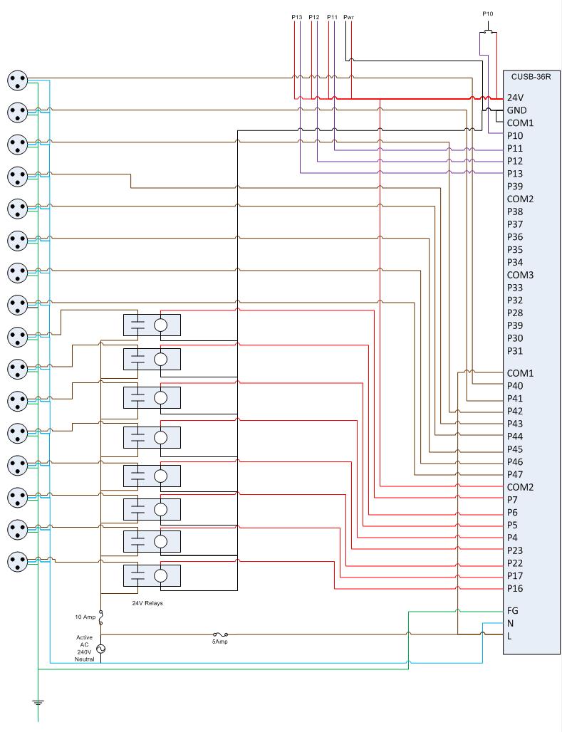
This is the circuit diagram for the Comfile CUSB-36R Programmed Christmas Lights. If it is difficult to read, please contact me via email at [email protected], and I will provide a more detailed schematic. The Comfile CUSB-36R can either drive...
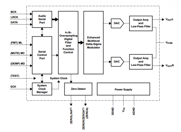
This document serves as a resource for developers who are new to Texas Instruments (TI) ARM-based processors, as well as for seasoned developers seeking to deepen their understanding of the different ARM architectures. It starts with an overview of...
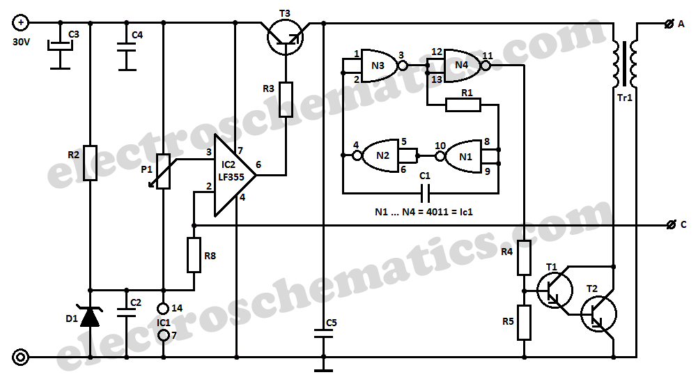
This DIY 12V to 220V DC to AC converter utilizes a CMOS 4047 as its main component, effectively transforming 12V DC into 220V AC. The circuit design of this DC to AC converter primarily revolves around the CMOS 4047 integrated...
It connects to the USB port and is ideal for checking motherboard switch and jumper settings. Many users may recall a commercial product of a similar nature. This device serves as a USB-based diagnostic tool designed to facilitate the verification...
Is there a source for a schematic for a USB to SPDIF converter, similar to those offered by Empirical Audio? The concept is appealing, but the price of $500 is quite high. A USB to SPDIF converter is a device...

A temperature-controlled pulse-width-modulator (PWM) boost converter circuit diagram is illustrated in the following figure. This boost converter is designed to operate a 12V fan using a 5V supply while maintaining temperature control. The temperature-controlled PWM boost converter circuit operates by...