
Design of Temperature-Controlled PWM Boost Converter Circuit

The temperature-controlled PWM boost converter circuit operates by stepping up a lower voltage (5V) to a higher voltage (12V) suitable for driving a fan. The circuit typically consists of several key components: a PWM controller, an inductor, a diode, a capacitor, and a temperature sensor.
The PWM controller modulates the duty cycle of the output voltage, allowing the fan speed to be adjusted based on temperature readings. The temperature sensor monitors the ambient temperature and sends feedback to the PWM controller. As the temperature increases, the PWM controller adjusts the duty cycle to increase the output voltage, thereby increasing the fan speed to enhance cooling. Conversely, as the temperature decreases, the fan speed is reduced to save power and minimize noise.
The inductor stores energy during the ON phase of the PWM signal and releases it during the OFF phase, contributing to the voltage boost. The diode allows current to flow in one direction, preventing backflow and ensuring efficient energy transfer to the output capacitor, which smooths the output voltage.
This configuration enables efficient thermal management in applications where temperature regulation is crucial, such as in electronic devices that generate heat. The ability to operate from a lower voltage supply while providing a higher output voltage makes this circuit versatile for various applications, including cooling systems in computers and other electronic equipment.Temperature controlled pulse-width-modulator (PWM) boost converter circuit diagram is shown in the following figure. The boost converter may provide temperature-controlled operation of 12V fan from 5V supply 🔗 External reference
Related Circuits
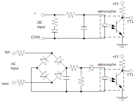
PLC input cards typically do not provide power, necessitating an external power supply for inputs and sensors. An example of an input card and a ladder logic diagram illustrates how to connect an AC input card. The PLC inputs...
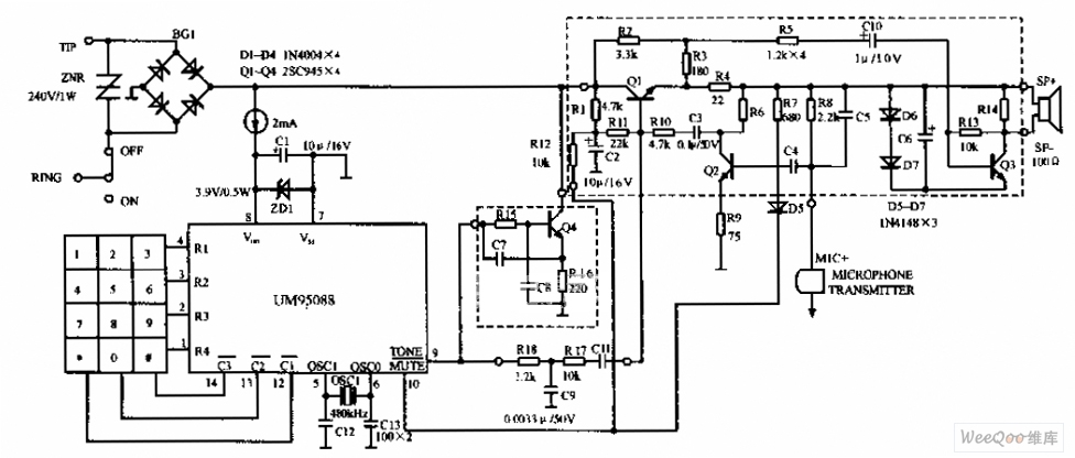
The UM95088 telephone circuit diagram is depicted in the image above. The UM95088 is a specialized integrated module designed for dual-tone multi-frequency (DTMF) telephone dialing. It utilizes CMOS technology and comes in a 14-pin dual-in-line package. The schematic for...
The completed board may be driven by voltages between 0.8 and 3 Volts. While the basic design goal was candle-like light from a single cell, the values used were chosen to allow safe operation from 3 Volts so you...
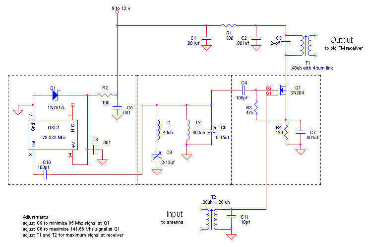
Here is my design for a modern receiving converter for pre-war FM sets. Accordingly, this article presents a design for listening to present day FM stations on a prewar FM set based on a MOSFET transistor and a TTL...
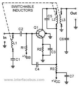
This page presents several transistor circuits that are not commonly found on other pages due to the absence of a specific topic. These circuits, however, illustrate particular points but lack detailed descriptions. An example of an RF amplifier circuit...
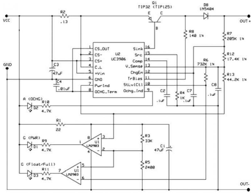
The UC3906 battery charger circuit controller includes all necessary circuitry to manage the charge and hold cycles for sealed lead-acid batteries. This circuit is specifically designed to deliver the appropriate charging voltage and current based on the battery's temperature...