
S1D15G10 Nokia LCD
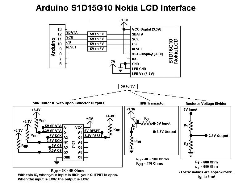
The operation of the color graphic LCD display relies on precise control of its interface signals and proper initialization as outlined in the datasheet. The Chip Select (CS) and RESET lines should be connected to the appropriate GPIO pins of a microcontroller, enabling the microcontroller to manage the display's state effectively. The configuration process typically involves setting up the display's contrast and initializing its RAM with specific data patterns to confirm that the display is operational.
The function `draw_text_line` is designed to render a line of text on the LCD. It takes parameters for foreground color (fcolor), background color (bcolor), and the coordinates (x, y) for positioning the text. The function first sets a bounding box for the text line using `lcd_set_box`, which defines the area of the display that will be affected. The command `sendCMD(RAMWR)` is issued to indicate that data will be written to the display's RAM.
A loop iterates over the bits of the character to determine how to render each pixel based on its value. The switch-case structure evaluates each bit of the character and sends the corresponding color data to the display. The use of bitwise operations allows for efficient manipulation of color values, ensuring that the correct colors are sent to the display based on the specified foreground and background colors.
To mitigate noise issues, which have been problematic in this project, implementing a ground plane using aluminum foil can help stabilize the signal integrity. The foil should be insulated and connected to the ground to reduce electromagnetic interference, which can affect the performance and reliability of the display. This additional measure, along with proper power supply considerations, can lead to improved operation of the LCD display in various applications.This is the first color, graphic LCD display I worked with. I made some assumptions when I first began working with it. From previously working with TTL logic in college, I assumed CS and RESET could just be tied high for simplicity. It wont work if you do that. They must be wired to the micro-controller to get reliable operation from the LCD. Tog gling them is necessary for normal operation. After wiring everything up, I desperately wanted some sign of life from the LCD, to know if it was wired correctly. Figuring out how to use the LCD without reading the datasheet is impossible. You could send random data to the display for a thousand years and never see any indication that it`s working.
Towards the end of the data sheet are application notes and a nice walk through for configuring the display. Usually, after setting the contrast for it, and writing some data to the display`s ram, you`ll see it do something.
Otherwise, simply powering the LCD and back-light (necessary) will give you a blue screen, and maybe just some sporadic lines from noise. Speaking of noise, this project has had the worst problems of any I`ve ever done. It`s probably been resolved by now with newer displays. Aside from using an external voltage booster for the backlight, an insulated foil ground plane could`ve been sandwiched between the display and breakout board.
Scotch tape on one side of aluminum foil, the side against the board, and connect the foil to ground. void NokiaLCD::draw_text_line(word fcolor, word bcolor, byte x, byte y, char c) { lcd_set_box(x, y, x, y+7); sendCMD(RAMWR); char i; for(i=0;i<4;i+) { switch( (0x03<<(i*2) & c) >> (i*2) ){ case 0x00: sendData(bcolor >> 4) & 0xFF); sendData(bcolor & 0xF) << 4) | (bcolor >> 8) & 0xF); sendData(bcolor & 0xFF); break; case 0x01: sendData(fcolor >> 4) & 0xFF); sendData(fcolor & 0xF) << 4) | (bcolor >> 8) & 0xF); sendData(bcolor & 0xFF); break; case 0x02: sendData(bcolor >> 4) & 0xFF); sendData(bcolor & 0xF) << 4) | (fcolor >> 8) & 0xF); sendData(fcolor & 0xFF); break; case 0x03: sendData(fcolor >> 4) & 0xFF); sendData(fcolor & 0xF) << 4) | (fcolor >> 8) & 0xF); sendData(fcolor & 0xFF); break; } } }
🔗 External reference
Related Circuits
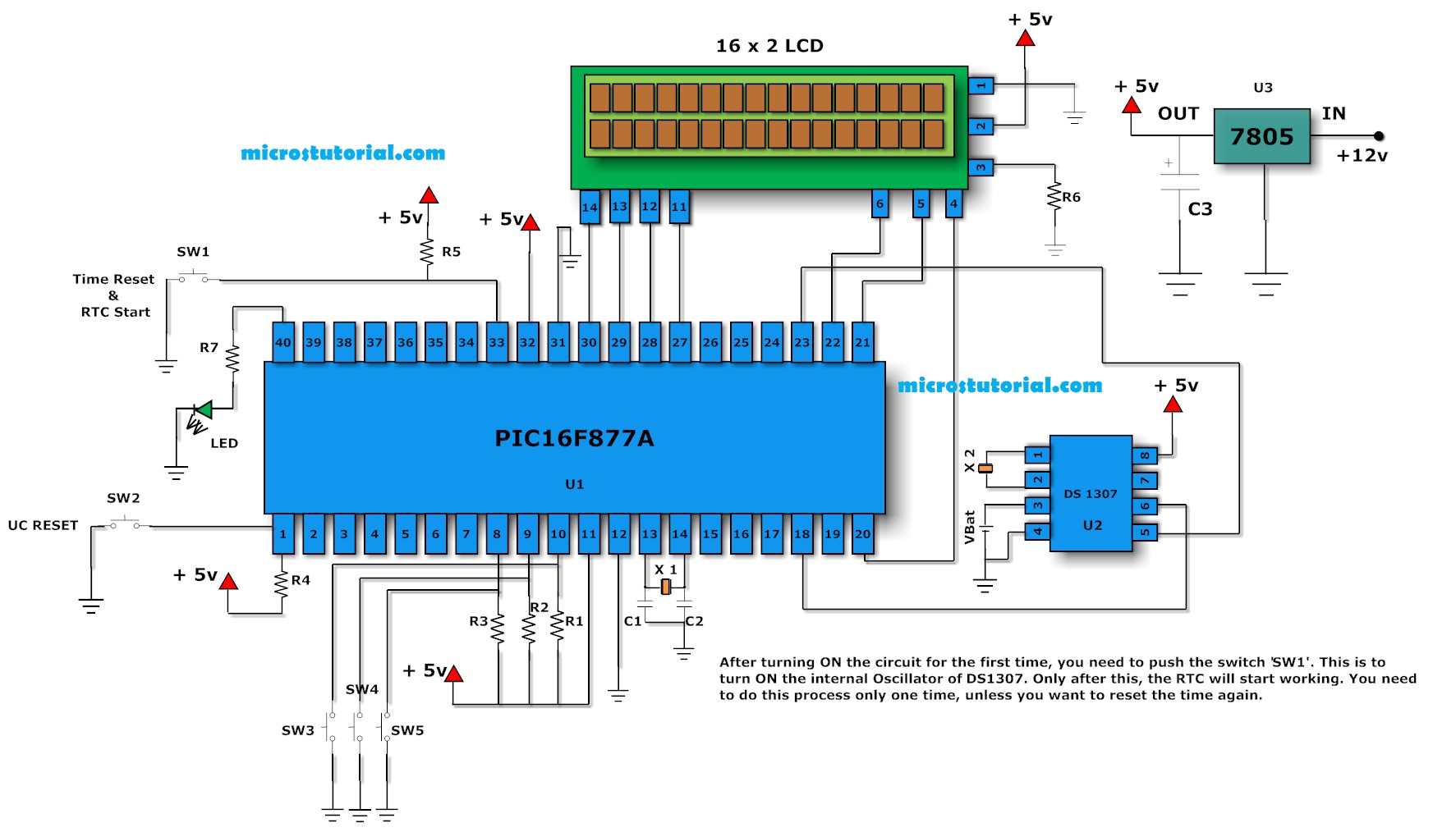
One of the main problems faced with an ordinary digital clock made using the PIC16F84 (or any other microcontrollers) is that it cannot maintain accurate time during power failures. When power fluctuations occur, the clock resets and starts counting...
Over time, microcontrollers have become increasingly powerful, cost-effective, and compact. A typical microcontroller from the past may have had 40 pins and lacked internal memory, whereas modern J-series PICs feature 96K of program memory and only 28 pins. This...
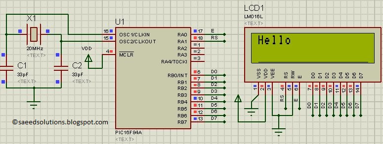
This post presents the LCD interfacing code utilizing the PIC16F84A microcontroller. The code is developed in the C programming language using MPLAB with the HI-TECH C compiler. The interfacing of an LCD (Liquid Crystal Display) with the PIC16F84A microcontroller...
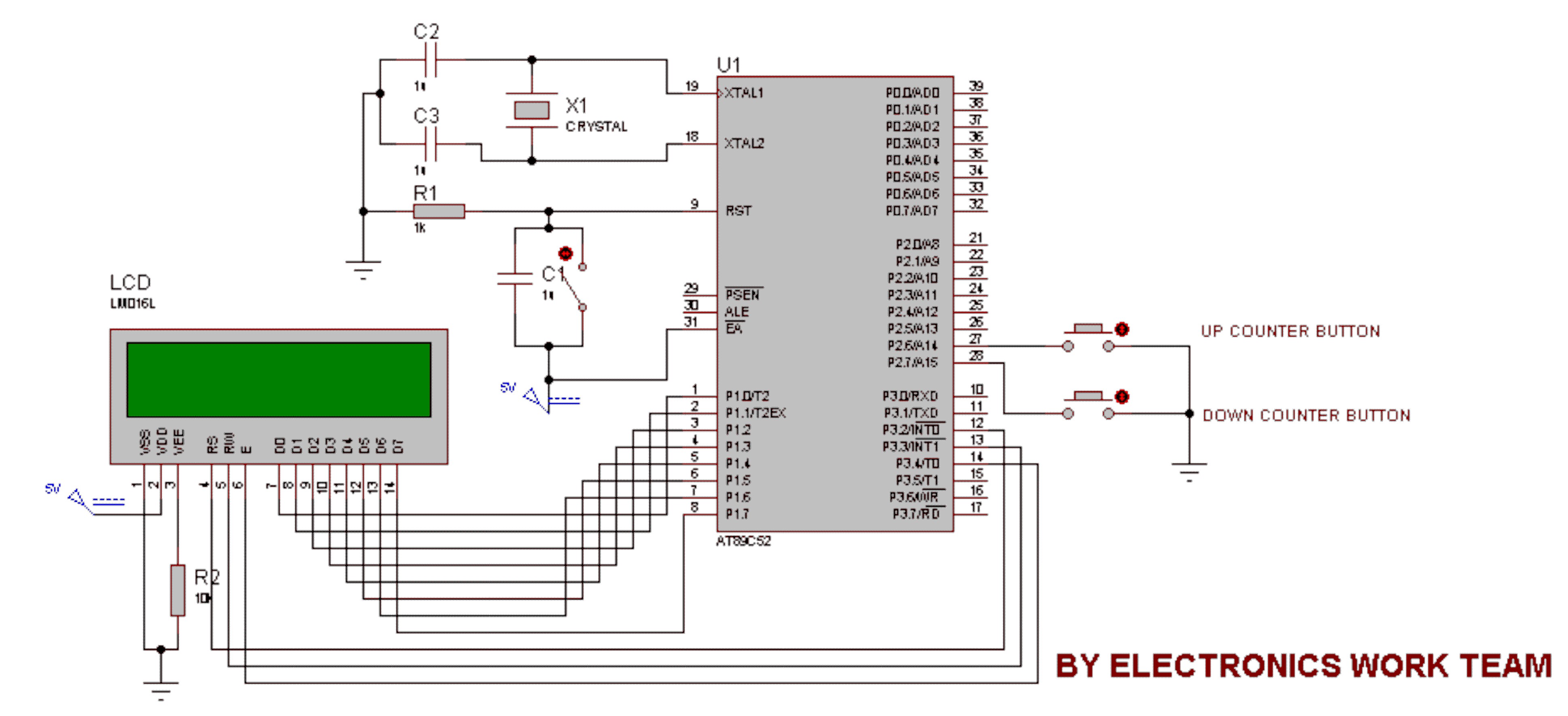
This circuit utilizes a 16x2 LCD to display a count value using an 8051 microcontroller. The maximum count value is set to 99. The circuit consists of the 8051 microcontroller, a 16x2 LCD, and two switches designated for incrementing...
An LCD essentially comprises two glass plates with a layer of liquid crystal material sandwiched between them. The LCD utilizes an electrically controlled light-polarizing liquid. The liquid crystal display (LCD) operates based on the manipulation of light through liquid crystals,...
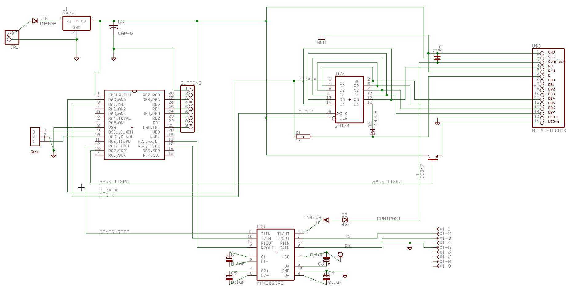
There is enough of poorly constructed RS232 alike TTL level interfaces (+5volt), this one generates its own +/- 10..11 volts as RS232 specs require, and is able to use very long cables like RS232 can, and protects computer as...