
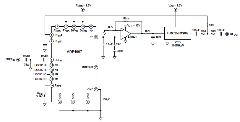
Schematic Diagram ADF-4007 6.7GHz Local oscillator circuit
The ADF4007 PLL synthesizer is a versatile component in modern communication systems, allowing for precise frequency generation and manipulation. Its ability to operate at high frequencies makes it ideal for applications that require stable and accurate local oscillators, such as satellite communications and cable television (CATV) systems. The integration of a low-noise digital phase frequency detector ensures that the system maintains high performance with minimal phase noise, which is crucial for maintaining signal integrity in high-frequency applications.
The prescaler function of the ADF4007 enhances its flexibility, allowing the user to select the appropriate division ratio for various applications. The fixed reference divider setting simplifies the design process, as it allows for straightforward calculations when determining the desired output frequency based on the input reference frequency.
In this specific configuration, the coupling capacitor used for AC coupling is critical for ensuring that the REFIN pin receives the correct biasing voltage of AVDD/2. The selection of the capacitor value is determined by the frequency of the input signal, and it must be chosen to ensure that the impedance presented to the REFIN pin remains below the specified threshold of 10 ohms. This is essential to minimize signal loss, which can adversely affect the performance of the PLL.
The charge pump output drives the loop filter, which is a vital component in determining the dynamic response of the PLL. The design of the loop filter must consider various factors, including the desired phase margin, which in this case is set at 45°. This phase margin is critical for ensuring stable operation of the PLL across its operating range, preventing oscillations and ensuring that the system can quickly lock onto the desired frequency.
Overall, the combination of the ADF4007 with the HMC358MS8G VCO creates a robust solution for generating a fixed-frequency local oscillator, capable of meeting the demands of high-frequency communication applications. The careful consideration of component values and configurations in this design ensures optimal performance and reliability.Using ADF4007 high frequency divider PLL synthesizer can be designed a variety of communications applications. It can operate to 7. 5 GHz on the RF side and to 120 MHz at the PFD. It consists of a low noise digital PFD (phase frequency detector), a precision charge pump, and a divider prescaler.
The divider prescaler value can be set by two externa l control pins to one of four values (8, 16, 32, or 64). The reference divider is permanently set to 2, allowing an external REFIN frequency of up to 240 MHz. This Local Oscillator electronic project use the ADF4007 with the HMC358MS8G VCO from Hittite Microwave Corporation to produce a fixed-frequency LO (local oscillator), which could be used in satellite or CATV applications.
In this case, the desired LO is 6. 7 GHz. To bias the REFIN pin at AVDD/2, ac coupling is used. The value of the coupling capacitor used depends on the input frequency. The equivalent impedance at the input frequency should be less than 10 ©. Given that the dc input impedance at the REFIN pin is 100 k ©, less than 0. 1% of the signal is lost. The charge pump output of the ADF4007 drives the loop filter. In calculating the loop filter component values, a number of items need to be considered. In this example, the loop filter was designed so that the overall phase margin for the system is 45 °. 🔗 External reference
Related Circuits
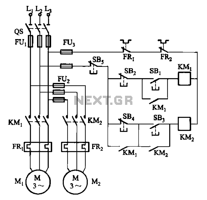
The circuit depicted in Figure 3-84 allows two electric motors to be started independently. The motors can only be activated after pressing the main stop button (SBz) to release contact KMi. Following this, the auxiliary stop button (SB4) can...
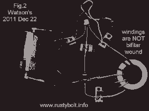
The coil must invert the signal a second time to ensure that the feedback is positive, which will cause the circuit to oscillate on and off. In electronic circuits, particularly in oscillator designs, the feedback mechanism plays a crucial role...
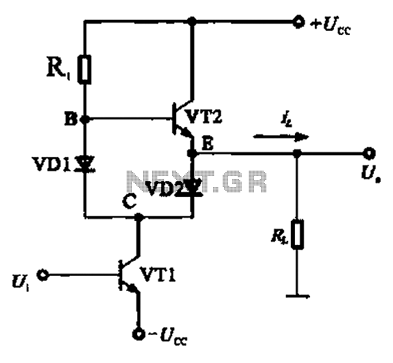
A Class AB output stage circuit is coupled with diodes, as illustrated in Figure 10-8. The static bias circuit for transistor VT1 (not shown) is adjusted so that the output at point E is at ground DC voltage UE....
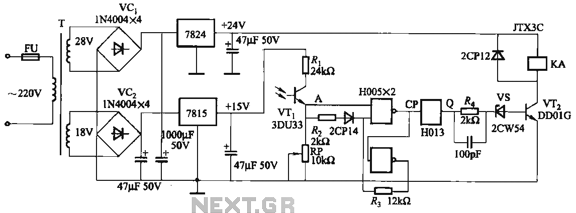
The circuit features a robust anti-jamming capability, making it suitable for demanding applications. It includes a phototransistor (VTi), a Schmitt trigger (H005), a JK flip-flop (H013), a power amplifier circuit, a relay (KA), and various actuators and other components....
Detects the amount of salt contained in liquid foods, featuring a three-level LED indicator. This circuit is designed to detect the approximate percentage of salt concentration. The salt detection circuit operates by utilizing a conductivity sensor that measures the ionic...

The circuit utilizes a 555 timer IC to create a lighting group delay effect, as illustrated in Figure 2-46. It consists of the 555 IC along with a resistor and capacitor configuration that establishes the delay. The circuit remains...