
Basic Theory Applied to Joule Thief circuit
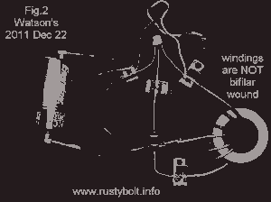
In electronic circuits, particularly in oscillator designs, the feedback mechanism plays a crucial role in determining the stability and oscillation frequency of the system. In this context, the coil serves as an essential component that contributes to the feedback loop. When the coil inverts the signal a second time, it reinforces the positive feedback necessary for oscillation.
This process can be understood in the framework of a basic feedback oscillator circuit, which typically includes an amplifier, a feedback network, and a frequency-determining element such as a coil or capacitor. The initial signal generated by the amplifier is fed back through the coil, where it undergoes phase inversion. For sustained oscillations, it is imperative that the feedback signal returns to the amplifier in phase with the original signal. This phase alignment ensures that the output of the amplifier continues to drive the circuit, resulting in repeated oscillation.
The oscillation frequency is primarily influenced by the inductance of the coil and the capacitance in the feedback loop. By selecting appropriate values for these components, designers can tailor the circuit to operate at specific frequencies. Additionally, the quality factor (Q) of the coil affects the sharpness of the resonance peak, which in turn influences the stability and amplitude of the oscillation.
In summary, the dual inversion of the signal by the coil is a fundamental aspect that enables the circuit to maintain positive feedback, thereby facilitating continuous oscillation. Proper design considerations regarding the coil and other reactive components are essential for achieving desired performance characteristics in oscillator circuits.Therefore the coil must invert it a second time in order for the feedback to be positive, and cause the circuit to oscillate on and off. 🔗 External reference
Related Circuits
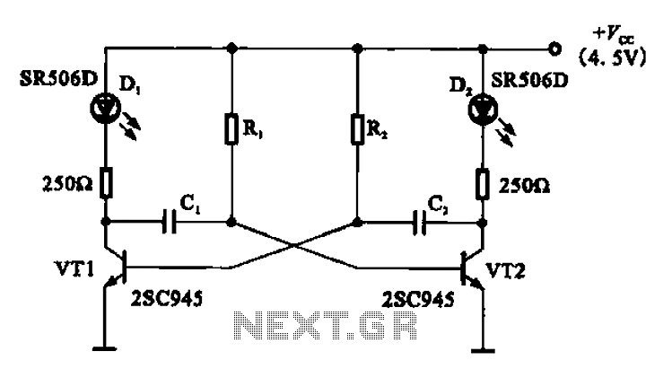
The multivibrator flashing light emitting diode (LED) display driver circuit can be utilized in toys, creating flashing effects in the eyes of animals or monsters. This circuit employs a multivibrator configuration, typically a 555 timer IC or a similar component,...
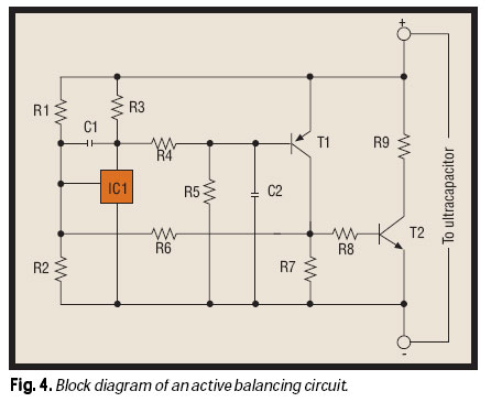
As the market seeks lighter, more compact wireless and portable devices with innovative features packed into increasingly constrained spaces, there is a concurrent pursuit for the next power supply innovation—a powerful, compact, long-lasting, economical, and safe battery. Although advancements...
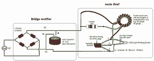
Breathe down and come out on the bright flashlight. In order to promote the voltage, pieces of a highly skilled Joule thief circuit have been used. The Joule thief circuit is a minimalist, low-power boost converter designed to extract energy...
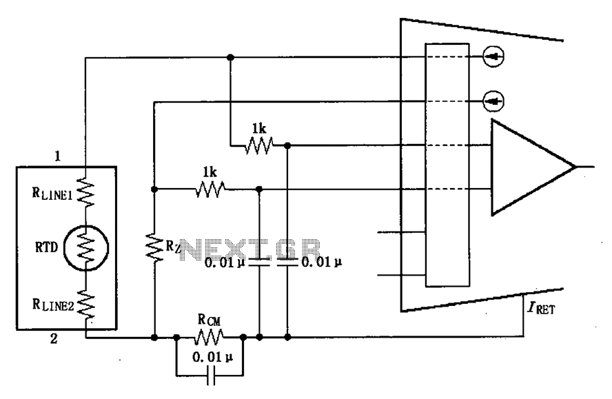
The long wire current loop transmission is susceptible to radio frequency (RF) interference, which can lead to errors in the sensitive input of the XTR108. This interference can occur particularly when the RTD sensor is located at a distance,...
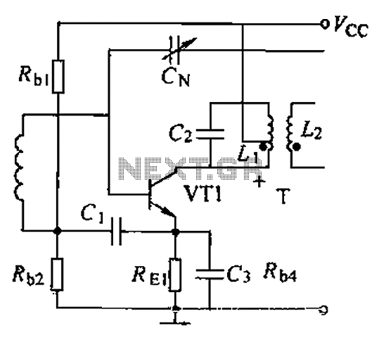
A common intermediate frequency amplifier circuit is presented, along with its components and parameters. The reference values for the components are as follows: 1) Transistors: VT1 to 3DG19, Vcc = 6V. 2) Resistance values: R1 = 50 kΩ, R2...
This project involves a straightforward soil moisture detection circuit that utilizes only four components and operates with a 3-volt battery. The circuit is designed to identify the presence of moisture in the soil of any plant and activate an...
Warning: include(partials/cookie-banner.php): Failed to open stream: Permission denied in /var/www/html/nextgr/view-circuit.php on line 713
Warning: include(): Failed opening 'partials/cookie-banner.php' for inclusion (include_path='.:/usr/share/php') in /var/www/html/nextgr/view-circuit.php on line 713