
Sensitive Overload Sensor
The circuit design for the sensitive overload indicator employs an operational amplifier (op-amp) configured in a comparator mode, which is adept at detecting voltage thresholds. The sense resistor (Rs) is strategically placed in series with the load to monitor the current flowing through it. The voltage across Rs is directly proportional to the current, following Ohm's law (V = I * R).
In this configuration, the op-amp's inverting input is connected to the junction of Rs and the diode (D1), while the non-inverting input is tied to a reference voltage derived from the positive supply. The Schottky diode is chosen for its low forward voltage drop, ensuring that the circuit can operate effectively even with minimal voltage differences.
R1, which is connected in series with the diode, serves to limit the current flowing through D1, thereby controlling the voltage drop across it. The design allows for fine-tuning of the sensitivity of the current detection. When the current exceeds a predetermined threshold, the voltage drop across Rs will surpass that across D1, causing the op-amp to switch its output state.
The output of the op-amp can drive an indicator lamp or relay, providing a visual or mechanical alert when an overload condition is detected. The circuit's ability to handle supply voltages of ±15 V makes it versatile for various applications, including industrial machinery, power supply monitoring, and safety systems. This design effectively balances the need for accurate current measurement with minimal impact on the circuit's overall performance.The best way to measure the current in a circuit is to place a sense resistor in the current path. The higher the resistance, the more exact the measurement will be. However, the drawback of a high resistance is that it affects the operation of the circuit in which the measurement is being made. If an active sort of sensor is used, the sense resis tance can be kept small. The circuit diagram shows how a sensitive overload indicator can be built using a simple opamp (such as an LF351) and a sense resistor in the current path. A voltage difference is generated between the plus and minus inputs of the opamp with the help of a diode.
Usually, the voltage drop across D1 (a Schottky diode) will be 0. 2 to 0. 3 V. This value can be influenced somewhat by R1, which affects the amount of current that flows through the diode. The larger the value of R1, the smaller the voltage drop across the diode. The inverting input of the opamp is connected to the positive supply voltage following the sense resistor Rs.
Consequently, the voltage level at the output of the opamp will be equal to the negative supply voltage, for example 5 V. As the current that‚ows through the sense resistor Rs increases, the voltage on the inverting input of the opamp decreases.
As soon as the voltage drop across Rs (= Is G— Rs) becomes slightly greater than the voltage drop across D1, the output of the opamp will switch to the positive supply voltage level. An indicator lamp or relay can be connected to the opamp output. The maximum supply voltage for the opamp is ±15 V, so the circuit can readily be used to monitor symmetric power supplies with voltages between 5 and 15V.
🔗 External reference
Related Circuits
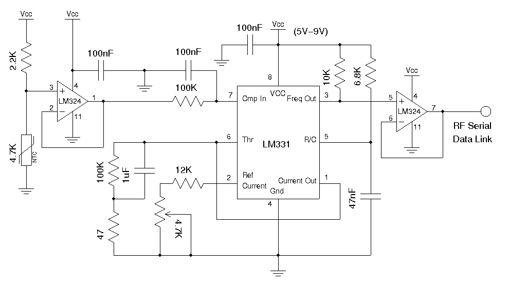
A wireless temperature sensor allows temperature measurements to be taken anywhere within the range of the transmitter and receiver. One straightforward approach to achieve this is by utilizing a voltage-to-frequency conversion chip in conjunction with an analog temperature sensor,...
The TMP03 is a complete temperature data-acquisition system on a monolithic silicon chip. Including a silicon-based sensor, internal voltage reference, and sigma-delta A/D converter, it fits in a 3-pin (power, common, and output) TO-92 transistor package. Its digital output...

This ultrasonic anemometer is designed for the two-dimensional measurement of horizontal wind speed components and wind direction, as well as virtual temperature. Due to its high measurement rate, the device effectively captures gusts and peak values without delay. The...
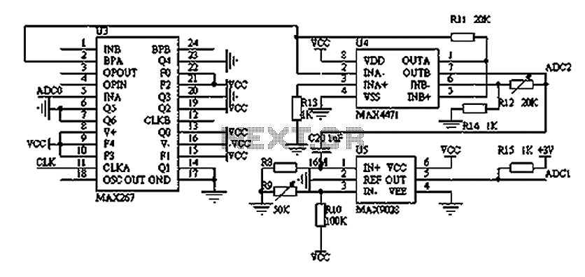
The filtering and amplifying circuit consists of two main components. The MAXIM MAX267 filter is an integrated circuit that can function as a low-pass, band-pass, high-pass filter, and other configurations, offering superior performance compared to traditional op-amp filters. The...
A rear fog lamp is mandatory for trailers and caravans to enhance visibility during foggy conditions. When the fog lamp is activated, the fog lamp of the towing vehicle must be turned off to prevent distracting reflections. To achieve...
A PIR sensor is triggered when using a timer to wait for 2 seconds after the sensor is activated. Without the timer, the sensor operates as intended. The PIR sensor is connected to an ATMega328p microcontroller, which has three...