
Sensitive RF Voltmeter Probe
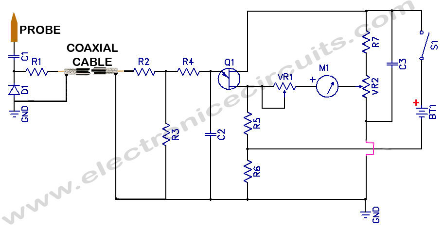
The sensitive RF voltmeter probe circuit is designed to accurately measure radio frequency (RF) voltages in the range exceeding 200 MHz, with a maximum output voltage of about 5V. This circuit typically employs a combination of high-frequency components, such as RF amplifiers, diodes, and filters, to ensure precision in voltage measurement at elevated frequencies.
Key components of the circuit may include a high-frequency operational amplifier configured as a voltage follower to minimize loading effects, allowing for accurate voltage readings without significantly affecting the circuit under test. Additionally, a suitable RF detector diode can be utilized to convert the RF voltage to a DC voltage, facilitating easier measurement with standard voltmeter equipment.
To enhance the performance of the probe, it is essential to incorporate proper impedance matching techniques, ensuring that the probe's input impedance aligns with the source impedance. This minimizes reflections and maximizes power transfer, which is critical in RF applications.
Furthermore, the circuit should include filtering components to eliminate unwanted noise and harmonics, ensuring that the measured voltage is representative of the actual RF signal. Capacitors and inductors may be strategically placed to form low-pass or band-pass filters, depending on the specific measurement requirements.
The overall design should consider the layout and shielding of the circuit to prevent interference from external sources, which could skew the measurements. A compact and robust PCB design will help maintain signal integrity and improve the reliability of the RF voltmeter probe circuit in practical applications.
In summary, this sensitive RF voltmeter probe circuit is a specialized tool for accurately measuring high-frequency voltages, making it invaluable in RF testing and measurement environments.Sensitive RF Voltmeter Probe Circuit This Circuit measures RF voltages beyond 200MHz and up to about 5V. PARTS.. 🔗 External reference
Related Circuits
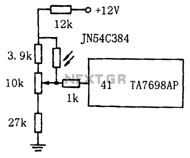
The circuit for automatic brightness adjustment in a television utilizes a photosensitive resistor and a contrast potentiometer connected to an intermediate stage. The photosensitive resistor varies its resistance based on light intensity, causing changes in the potential at the...
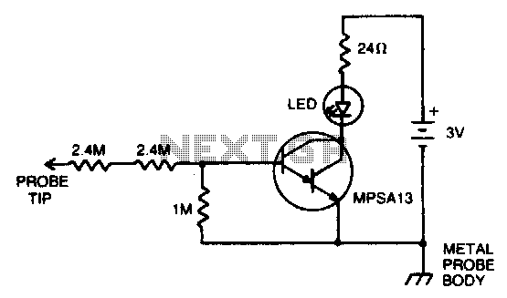
Insert the probe tip into either terminal of an AC outlet and hold the probe body against any object that the circuit ground is connected to. The LED will illuminate when the hot terminal is touched. Two 2 MΩ...
The figure illustrates the schematic for a versatile logic probe. The zener diode clamps the input signal slightly above the TTL inverter's 2.2-V trigger voltage. Zener diode D1 can be omitted if the probe is intended solely for use...
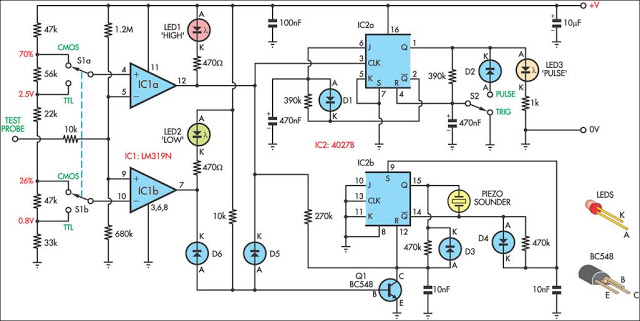
This logic probe can be selected to operate on TTL or CMOS logic levels, depending on switch S1. A string of resistors associated with switch S1 sets the threshold levels for a window comparator comprising IC1a and IC1b. Depending...
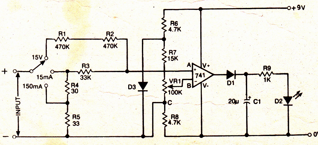
A simple electronic multimeter offers an affordable alternative for hobbyists deterred by the high cost of conventional multimeters. This device is designed to measure three ranges: (i) 0-15V, (ii) 0-15mA, and (iii) 0-150mA, with the possibility of extending the...
This circuit provides a straightforward method for measuring the voltage of a low-impedance voltage source. It operates as follows: P1, a 1-W potentiometer, acts as a voltage divider in conjunction with resistor R1. The voltage at their junction is...